- 您现在的位置:买卖IC网 > PDF目录373745 > TSS463D Industrial Control IC PDF资料下载
参数资料
| 型号: | TSS463D |
| 英文描述: | Industrial Control IC |
| 中文描述: | 工业控制IC |
| 文件页数: | 17/52页 |
| 文件大小: | 268K |
| 代理商: | TSS463D |
第1页第2页第3页第4页第5页第6页第7页第8页第9页第10页第11页第12页第13页第14页第15页第16页当前第17页第18页第19页第20页第21页第22页第23页第24页第25页第26页第27页第28页第29页第30页第31页第32页第33页第34页第35页第36页第37页第38页第39页第40页第41页第42页第43页第44页第45页第46页第47页第48页第49页第50页第51页第52页
TSS461C
17
Rev. D (22 Feb 01)
8. Diagnosis System
The purpose of the diagnosis system is to detect any short or open circuits on either the DATA or DATA lines
and to permit, if it is possible, to carry the communications on the non-defective line.
The diagnosis system is based on the assumption that three separate line receivers are connected to the VAN bus (c.f.
Figure 3. ):
One of the line receivers is connected in differential mode, sensing both DATA and DATA signals, and is connected
to the RxD0 input.
The other two line receivers are operating in single wire mode and are sensing only one of the two VAN bus signals:
the line receiver sensing DATA is connected to RxD1,
the line receiver sensing DATA is connected to RxD2.
The diagnosis system analyses and compares the data sent over both VAN lines. So, the diagnosis system executes a
digital filtering and transition analyses. In order to perform its investigation, three internal signals are generated, RI
(
Return to Idle)
, SDC (
Synchronous Diagnosis Clock)
and TIP (
Transmission In Progress
).
One of four operating modes can be chosen to manage the results of the diagnosis system.
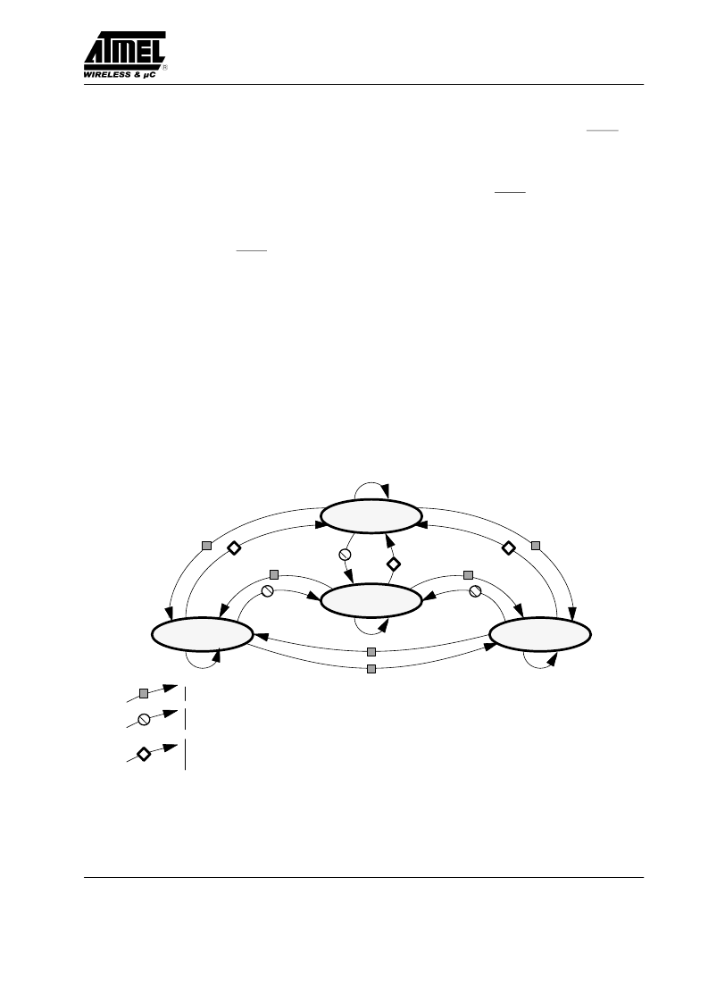
8.1. Diagnosis States
If the diagnosis system finds a failure on either of the VAN bus signals, it changes from nominal to degraded mode,
and connects the line receiver not coupled to the failing signal to the reception logic.
When the diagnosis system finds that the failing signal is working again, it returns to nominal mode and re-connects
the differential line receiver to the reception logic.
A major error occurs when both the VAN bus signals are failed.
NONIMAL
MAJOR
ERROR
DEGRATED
DATA
DEGRATED
DATA
- Failure during the frame.
- Default of transitions on the valid input between 2 consecutive SDC rising edges.
- Protocol fault
- In specified selection mode, every RI pulse when an EOF is detected or through an active SDC.
- In automatic selection mode and SDC active, no failure sampled by 2 consecutive SDC rising edges.
- General reset
Figure 17. Diagnosis States
相关PDF资料 |
PDF描述 |
|---|---|
| TSS463R | Industrial Control IC |
| TSS461E | VAN Data Link Controller |
| TSS461E-TDRA-9 | VAN Data Link Controller |
| TSS461E-TERA-9 | VAN Data Link Controller |
| TSS461E-TRDZ-9 | VAN Data Link Controller |
相关代理商/技术参数 |
参数描述 |
|---|---|
| TSS463R | 制造商:未知厂家 制造商全称:未知厂家 功能描述:Industrial Control IC |
| TSS463VAN | 制造商:TEMIC 制造商全称:TEMIC Semiconductors 功能描述:Van Controller Serial Interface |
| TSS47 | 功能描述:瓷片电容器 100V 20% 0.047uF RoHS:否 制造商:Vishay/Cera-Mite 电容:0.01 uF 容差:20 % 电压额定值:3 kV 工作温度范围:- 25 C to + 105 C 损耗因数 DF: 端接类型:Radial 产品:High Voltage Ceramic Disc Capacitors |
| TSS4B01G | 功能描述:整流器 4.0 Amp 50 Volt 150 Amp IFSM RoHS:否 制造商:Vishay Semiconductors 产品:Standard Recovery Rectifiers 配置: 反向电压:100 V 正向电压下降: 恢复时间:1.2 us 正向连续电流:2 A 最大浪涌电流:35 A 反向电流 IR:5 uA 安装风格:SMD/SMT 封装 / 箱体:DO-221AC 封装:Reel |
| TSS4B01G C2 | 制造商:SKMI/Taiwan 功能描述:Diode Rectifier Bridge Single 50V 4A 4-Pin TS4B Tube |
发布紧急采购,3分钟左右您将得到回复。