- 您现在的位置:买卖IC网 > PDF目录18805 > TXM-916-ES_ (Linx Technologies Inc)TRANSMITTER RF 916MHZ 10PIN SMD PDF资料下载
参数资料
| 型号: | TXM-916-ES_ |
| 厂商: | Linx Technologies Inc |
| 文件页数: | 5/11页 |
| 文件大小: | 0K |
| 描述: | TRANSMITTER RF 916MHZ 10PIN SMD |
| 产品变化通告: | ES Series Frequency Change 22/Dec/2010 |
| 产品目录绘图: | TXM-916-ES Top TXM-916-ES Side |
| 标准包装: | 40 |
| 系列: | ES |
| 频率: | 916MHz |
| 应用: | 住宅/楼宇自动化,工业控制和监控 |
| 调制或协议: | AM,OOK |
| 数据传输率 - 最大: | 56 kbps |
| 功率 - 输出: | 4dBm |
| 电流 - 传输: | 8.5mA |
| 数据接口: | PCB,表面贴装 |
| 天线连接器: | PCB,表面贴装 |
| 电源电压: | 2.1 V ~ 4 V |
| 工作温度: | 0°C ~ 70°C |
| 封装/外壳: | 模块 |
| 包装: | 散装 |
| 其它名称: | TXM-916-ES TXM-916-ES_-ND TXM916ES |
�� �
�
�PROTOCOL� GUIDELINES�
�While� many� RF� solutions� impose� data� formatting� and� balancing� requirements,�
�Linx� RF� modules� do� not� encode� or� packetize� the� signal� content� in� any� manner.�
�The� received� signal� will� be� affected� by� such� factors� as� noise,� edge� jitter,� and�
�interference,� but� it� is� not� purposefully� manipulated� or� altered� by� the� modules.�
�This� gives� the� designer� tremendous� flexibility� for� protocol� design� and� interface.�
�Despite� this� transparency� and� ease� of� use,� it� must� be� recognized� that� there� are�
�distinct� differences� between� a� wired� and� a� wireless� environment.� Issues� such� as�
�interference� and� contention� must� be� understood� and� allowed� for� in� the� design�
�process.� To� learn� more� about� protocol� considerations,� we� suggest� you� read� Linx�
�Application� Note� AN-00160.�
�Errors� from� interference� or� changing� signal� conditions� can� cause� corruption� of�
�the� data� packet,� so� it� is� generally� wise� to� structure� the� data� being� sent� into� small�
�packets.� This� allows� errors� to� be� managed� without� affecting� large� amounts� of�
�data.� A� simple� checksum� or� CRC� could� be� used� for� basic� error� detection.� Once�
�an� error� is� detected,� the� protocol� designer� may� wish� to� simply� discard� the� corrupt�
�data� or� implement� a� more� sophisticated� scheme� to� correct� it.�
�INTERFERENCE� CONSIDERATIONS�
�TYPICAL� APPLICATIONS�
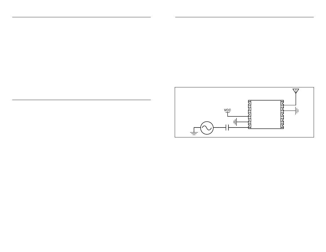
�USING� THE� ES� SERIES� TRANSMITTER� FOR� ANALOG� APPLICATIONS�
�The� ES� Series� is� an� excellent� choice� for� sending� analog� information,� including�
�audio.� The� ability� of� the� ES� to� transmit� combinations� of� analog� and� digital� content�
�opens� many� new� opportunities� for� design� creativity.�
�Simple� or� complex� analog� signals� within� the� specified� audio� bandwidth� and� input�
�levels� may� be� connected� directly� to� the� transmitter’s� DATA� line.� The� transmitter�
�input� is� high� impedance� (500k� Ω� )� and� can� be� directly� driven� by� a� wide� variety� of�
�sources,� ranging� from� a� single� frequency� to� complex� content,� such� as� audio.�
�Analog� sources� should� provide� 0V� to� no� more� than� 5V� P-P� maximum� waveform�
�and� should� be� AC-coupled� into� the� DATA� line.� The� size� of� the� coupling� capacitor�
�should� be� large� enough� to� ensure� the� passage� of� all� desired� frequencies.� Since�
�the� modulation� voltage� applied� to� the� DATA� line� determines� the� carrier� deviation,�
�distortion� can� occur� if� the� DATA� line� is� over-driven.� The� actual� level� of� the� input�
�waveform� should� be� adjusted� to� achieve� optimum� in-circuit� results.�
�The� RF� spectrum� is� crowded� and� the� potential� for� conflict� with� other� unwanted�
�sources� of� RF� is� very� real.� While� all� RF� products� are� at� risk� from� interference,� its�
�1�
�2�
�PDN�
�LADJ�
�ANT�
�GND�
�10�
�9�
�effects� can� be� minimized� by� better� understanding� its� characteristics.�
�3�
�VCC� LO_V_D�
�8�
�Interference� may� come� from� internal� or� external� sources.� The� first� step� is� to�
�eliminate� interference� from� noise� sources� on� the� board.� This� means� paying�
�careful� attention� to� layout,� grounding,� filtering,� and� bypassing� in� order� to�
�0-Vcc� Audio� Source�
�4�
�5�
�GND�
�DATA�
�/CLK� SE�
�/CLK�
�7�
�6�
�eliminate� all� radiated� and� conducted� interference� paths.� For� many� products,� this�
�is� straightforward;� however,� products� containing� components� such� as� switching�
�power� supplies,� motors,� crystals,� and� other� potential� sources� of� noise� must� be�
�approached� with� care.� Comparing� your� own� design� with� a� Linx� evaluation� board�
�can� help� to� determine� if� and� at� what� level� design-specific� interference� is� present.�
�External� interference� can� manifest� itself� in� a� variety� of� ways.� Low-level�
�interference� will� produce� noise� and� hashing� on� the� output� and� reduce� the� link’s�
�overall� range.�
�High-level� interference� is� caused� by� nearby� products� sharing� the� same�
�frequency� or� from� near-band� high-power� devices.� It� can� even� come� from� your�
�own� products� if� more� than� one� transmitter� is� active� in� the� same� area.� It� is�
�important� to� remember� that� only� one� transmitter� at� a� time� can� occupy� a�
�frequency,� regardless� of� the� coding� of� the� transmitted� signal.� This� type� of�
�interference� is� less� common� than� those� mentioned� previously,� but� in� severe�
�cases� it� can� prevent� all� useful� function� of� the� affected� device.�
�Although� technically� it� is� not� interference,� multipath� is� also� a� factor� to� be�
�understood.� Multipath� is� a� term� used� to� refer� to� the� signal� cancellation� effects�
�that� occur� when� RF� waves� arrive� at� the� receiver� in� different� phase� relationships.�
�This� effect� is� a� particularly� significant� factor� in� interior� environments� where�
�objects� provide� many� different� signal� reflection� paths.� Multipath� cancellation�
�results� in� lowered� signal� levels� at� the� receiver� and,� thus,� shorter� useful� distances�
�for� the� link.�
�Page� 8�
�0.1μF�
�Figure� 10:� AC� Coupling� An� Audio� Source�
�USING� THE� ES� SERIES� TRANSMITTER� FOR� DIGITAL� APPLICATIONS�
�The� ES� Series� transmitter� is� equally� capable� at� accommodating� digital� data.� The�
�transmitter� input� is� high� impedance� (500k)� and� can� be� directly� driven� by� a� wide�
�variety� of� sources� including� microprocessors� and� encoder� ICs.�
�When� the� transmitter� will� be� used� to� transmit� digital� data,� the� DATA� line� is� best�
�driven� from� a� 3� to� 5V� source.� The� transmitter� is� designed� to� give� an� average�
�deviation� of� 115kHz� with� a� 5V� square� wave� input,� and� 75kHz� with� 3V� square�
�wave� input.� Either� choice� will� achieve� maximum� performance.�
�Data� adhering� to� different� electrical� level� standards,� such� as� RS-232,� will� require�
�buffering� or� conversion� to� logic� level� voltages.� In� the� case� of� RS-232,� such�
�buffering� is� easily� handled� with� widely� available� ICs,� such� as� the� MAX232,� which�
�is� used� on� the� ES� Series� Master� Development� System.� The� Linx� SDM-USB-QS�
�can� be� used� to� convert� between� USB� compliant� signals� and� logic� level� voltages.�
�Page� 9�
�相关PDF资料 |
PDF描述 |
|---|---|
| R9G22612CSOO | RECTIFIER FAST REC 2600V 1200A |
| D2VW-01-3HS | MINIATURE BASIC SWITCH |
| 601W-36-S | LEAD TEST MINIHK-BANAPLG SET/10 |
| FXO-HC736R-45.1584 | OSC 45.1584 MHZ 3.3V HCMOS SMD |
| 681-36-S | LEAD TEST ALLIGCLP-BANAPLG SET10 |
相关代理商/技术参数 |
参数描述 |
|---|---|
| TXM-916-ES_ | 功能描述:TRANSMITTER RF 916MHZ 10PIN SMD RoHS:是 类别:RF/IF 和 RFID >> RF 发射器 系列:ES 标准包装:4,000 系列:- 频率:310MHz ~ 440MHz 应用:- 调制或协议:UHF,ASK 数据传输率 - 最大:20 kBaud 功率 - 输出:1dBm ~ 5dBm 电流 - 传输:10mA 数据接口:PCB,表面贴装 天线连接器:PCB,表面贴装 存储容量:- 特点:- 电源电压:2.2 V ~ 4 V 工作温度:-40°C ~ 85°C 封装/外壳:16-LSSOP(0.154",3.90mm 宽) 包装:带卷 (TR) |
| TX-MVX | 制造商:Radio Design Labs 功能描述:Two Bnc In, Single Bnc Out Manual Video Switch 制造商:RADIO DESIGN LABS 功能描述:MANUAL VIDEO SWITCH TWO BNC IN, SINGLE BNC OUT |
| TX-MX2R | 制造商:Radio Design Labs 功能描述:Mixer /Distribution Amplifier 制造商:RADIO DESIGN LABS 功能描述:MIXER /DISTRIBUTION AMPLIFIER |
| TXN/A10NCSS | 制造商:Panasonic Industrial Company 功能描述:PC BOARD |
| TXN/A10QBMS | 制造商:Panasonic Industrial Company 功能描述:PC BOARD |
发布紧急采购,3分钟左右您将得到回复。