- 您现在的位置:买卖IC网 > PDF目录245265 > UC1834L883B (TEXAS INSTRUMENTS INC) 1-CHANNEL POWER SUPPLY SUPPORT CKT, CQCC20 PDF资料下载
参数资料
| 型号: | UC1834L883B |
| 厂商: | TEXAS INSTRUMENTS INC |
| 元件分类: | 电源管理 |
| 英文描述: | 1-CHANNEL POWER SUPPLY SUPPORT CKT, CQCC20 |
| 封装: | CERAMIC, LCC-20 |
| 文件页数: | 4/11页 |
| 文件大小: | 849K |
| 代理商: | UC1834L883B |
ABSOLUTE MAXIMUM RATINGS (Note 1)
Input Supply Voltage, VIN + . . . . . . . . . . . . . . . . . . . . . . . . . 40V
Driver Current . . . . . . . . . . . . . . . . . . . . . . . . . . . . . . . . . 400mA
Driver Source to Sink Voltage . . . . . . . . . . . . . . . . . . . . . . . 40V
Crowbar Current . . . . . . . . . . . . . . . . . . . . . . . . . . . . . .
200mA
+1.5V Reference Output Current . . . . . . . . . . . . . . . . . .
10mA
Fault Alert Voltage . . . . . . . . . . . . . . . . . . . . . . . . . . . . . . . . 40V
Fault Alert Current . . . . . . . . . . . . . . . . . . . . . . . . . . . . . . 15mA
Error Amplifier Inputs . . . . . . . . . . . . . . . . . . . . . .
0.5V to 35V
Current Sense Inputs . . . . . . . . . . . . . . . . . . . . . .
0.5V to 40V
O.V. Latch Output Voltage . . . . . . . . . . . . . . . . . .
0.5V to 40V
O.V. Latch Output Current . . . . . . . . . . . . . . . . . . . . . . . . 15mA
Power Dissipation at TA = 25°C . . . . . . . . . . . . . . . . . . 1000mW
Power Dissipation at TC = 25°C. . . . . . . . . . . . . . . . . . 2000mW
Operating Junction Temperature . . . . . . . . . .
55°C to +150°C
Storage Temperature . . . . . . . . . . . . . . . . . . .
65°C to +150°C
Lead Temperature (soldering, 10 seconds). . . . . . . . . . . 300°C
Note 1: Voltages are reference to VIN
, Pin 5.
Currents are positive into, negative out of the specified
terminals.
Consult Packaging section of Databook for thermal
limitations and considerations of package.
UC1834
UC2834
UC3834
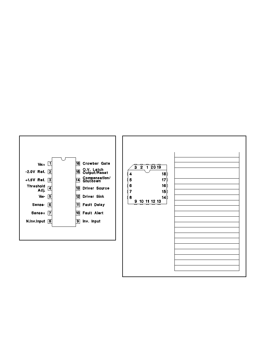
CONNECTION DIAGRAMS
DIL-16, SOIC-16 (TOP VIEW)
J or N Package, DW Package
PLCC-20, LCC-20 (TOP VIEW)
Q, L Packages
PACKAGE PIN FUNCTION
FUNCTION
PIN
N/C
1
VIN +
2
2.0V REF
3
+1.5V REF
4
Threshold Adjust
5
N/C
6
VIN
7
Sense
8
Sense+
9
N.Inv. Input
10
N/C
11
Inv. Input
12
Fault Alert
13
Fault Delay
14
Driver Sink
15
N/C
16
Driver Source
17
Compensation/ Shutdown
18
O.V. Latch Output/Reset
19
Crowbar Gate
20
2
相关PDF资料 |
PDF描述 |
|---|---|
| UC1841J/883BC | 1 A SWITCHING CONTROLLER, 500 kHz SWITCHING FREQ-MAX, CDIP18 |
| UC3823DW | 2 A SWITCHING CONTROLLER, 1000 kHz SWITCHING FREQ-MAX, PDSO16 |
| UC1847L | 0.5 A SWITCHING CONTROLLER, 500 kHz SWITCHING FREQ-MAX, CQCC20 |
| V54C3256164VBF7 | 16M X 16 SYNCHRONOUS DRAM, 5.4 ns, PBGA60 |
| V54C3256164VBJ7PC | 16M X 16 SYNCHRONOUS DRAM, 5.4 ns, PBGA60 |
相关代理商/技术参数 |
参数描述 |
|---|---|
| UC1834LQMLV | 制造商:Texas Instruments 功能描述:LDO CNTRLR REG 1.5V 20LCCC - Rail/Tube |
| UC1835 | 制造商:TI 制造商全称:Texas Instruments 功能描述:High Efficiency Regulator Controller |
| UC1835J | 制造商:Rochester Electronics LLC 功能描述:- Bulk |
| UC1835L | 制造商:Texas Instruments 功能描述:LDO CNTRLR REG 5V 20PLCC - Rail/Tube |
| UC1836 | 制造商:TI 制造商全称:Texas Instruments 功能描述:High Efficiency Regulator Controller |
发布紧急采购,3分钟左右您将得到回复。