- 您现在的位置:买卖IC网 > PDF目录276628 > VI-ARM-M1F 1-OUTPUT 500 W AC-DC REG PWR SUPPLY MODULE PDF资料下载
参数资料
| 型号: | VI-ARM-M1F |
| 元件分类: | 电源模块 |
| 英文描述: | 1-OUTPUT 500 W AC-DC REG PWR SUPPLY MODULE |
| 封装: | ROHS COMPLIANT PACKAGE-7 |
| 文件页数: | 10/11页 |
| 文件大小: | 705K |
| 代理商: | VI-ARM-M1F |
Vicor Corp. Tel: 800-735-6200, 978-470-2900 Fax: 978-475-6715
ARM, Autoranging Rectifier Module
Rev. 3.9
Page 8 of 11
Set your site on VICOR at vicorpower.com
APPLICATION NOTE (CONT.)
Operating Power (W)
P
o
wer
F
ail
W
arning
Time
(ms)
0
5
10
15
20
25
30
35
40
1500
1250
1000
750
500
250
*
2,200
μF
1,600
μF
1,300
μF
*
1,100
μF
820
μF
680
μF (VI-ARM-x1)
(VI-ARMB-x2)
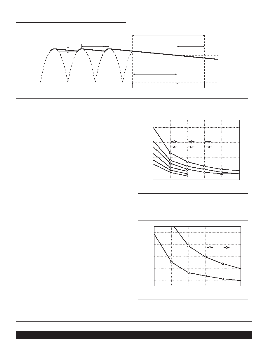
Figure 15 — Power fail warning time vs. operating power and
total bus capacitance, series combination of C1, C2 (Fig. 10)
Operating Power (W)
Ride
–Through
Time
(ms)
0
10
20
30
40
50
60
70
80
90
100
90 Vac
115 Vac
1500
1250
1000
750
500
250
Total
capacitance
820
μF
Figure 16 — Ride-through time vs. operating power
Figure 14 — Hold-up time
205 V
190 V
Power Fail
Warning
Bus OK
Converter
Shut down
Hold-up Time
254 V
Ride-Through Time
Ripple (V p-p)
π – θθ
The power fail warning time (
Δt) is defined as the interval
between (B OK) and converter shutdown (EN) as illustrated in
Fig. 12. The Bus-OK and Enable thresholds are 205 V and
190 V, respectively. A simplified relationship between power
fail warning time, operating power, and bus capacitance is
obtained by inserting these constants:
C = 2P
Δt / (2052 – 1902)
C = 2P
Δt / (5,925)
It should be noted that the series combination (C1, C2, Fig. 10)
requires each capacitor to be twice the calculated value,
but the required voltage rating is reduced to 200 V.
Allowable ripple voltage on the bus (or ripple current in the
capacitors) may define the capacitance requirement.
Consideration should be given to converter ripple rejection and
resulting output ripple voltage.
For example, a converter whose output is 15 V and nominal
input is 300 V will provide 56 dB ripple rejection, i.e., 10 V p-p
of input ripple will produce 15 mV p-p of output ripple. (See
Fig. 18
) Equation 3 is again used to determine the required
capacitance. In this case, V1 and V2 are the instantaneous
values of bus voltage at the peaks and valleys (see Fig. 14) of
the ripple, respectively. The capacitors must hold up the bus
voltage for the time interval (
Δt) between peaks of the rectified
line as given by:
Δt = (π – θ) / 2πf(4)
Where:
f = line frequency
θ = rectifier conduction angle
The approximate conduction angle is given by:
θ = Cos-1V
2/V1
(5)
相关PDF资料 |
PDF描述 |
|---|---|
| VRPB-10D50SG | 1-OUTPUT 50 W DC-DC REG PWR SUPPLY MODULE |
| V24A15C400AL | 1-OUTPUT 400 W DC-DC REG PWR SUPPLY MODULE |
| V300C1V8C45AN3 | 1-OUTPUT 45 W DC-DC REG PWR SUPPLY MODULE |
| V24A24C400AN3 | 1-OUTPUT 400 W DC-DC REG PWR SUPPLY MODULE |
| V375C12H150AL2 | 1-OUTPUT 150 W DC-DC REG PWR SUPPLY MODULE |
相关代理商/技术参数 |
参数描述 |
|---|---|
| VI-ARM-M1N | 制造商:VICOR 制造商全称:Vicor Corporation 功能描述:Autoranging Rectifier Modules Up to 1500 Watts |
| VI-ARM-M1S | 制造商:VICOR 制造商全称:Vicor Corporation 功能描述:Autoranging Rectifier Modules Up to 1500 Watts |
| VI-ARM-M21 | 制造商:VICOR 制造商全称:Vicor Corporation 功能描述:Autoranging Rectifier Modules Up to 1500 Watts |
| VI-ARM-M22 | 制造商:VICOR 制造商全称:Vicor Corporation 功能描述:Autoranging Rectifier Modules Up to 1500 Watts |
| VI-ARM-M2N | 制造商:VICOR 制造商全称:Vicor Corporation 功能描述:Autoranging Rectifier Modules Up to 1500 Watts |
发布紧急采购,3分钟左右您将得到回复。