- 您现在的位置:买卖IC网 > PDF目录361765 > W149H CPU System Clock Generator PDF资料下载
参数资料
| 型号: | W149H |
| 英文描述: | CPU System Clock Generator |
| 中文描述: | CPU系统时钟发生器 |
| 文件页数: | 13/15页 |
| 文件大小: | 151K |
| 代理商: | W149H |
W149
13
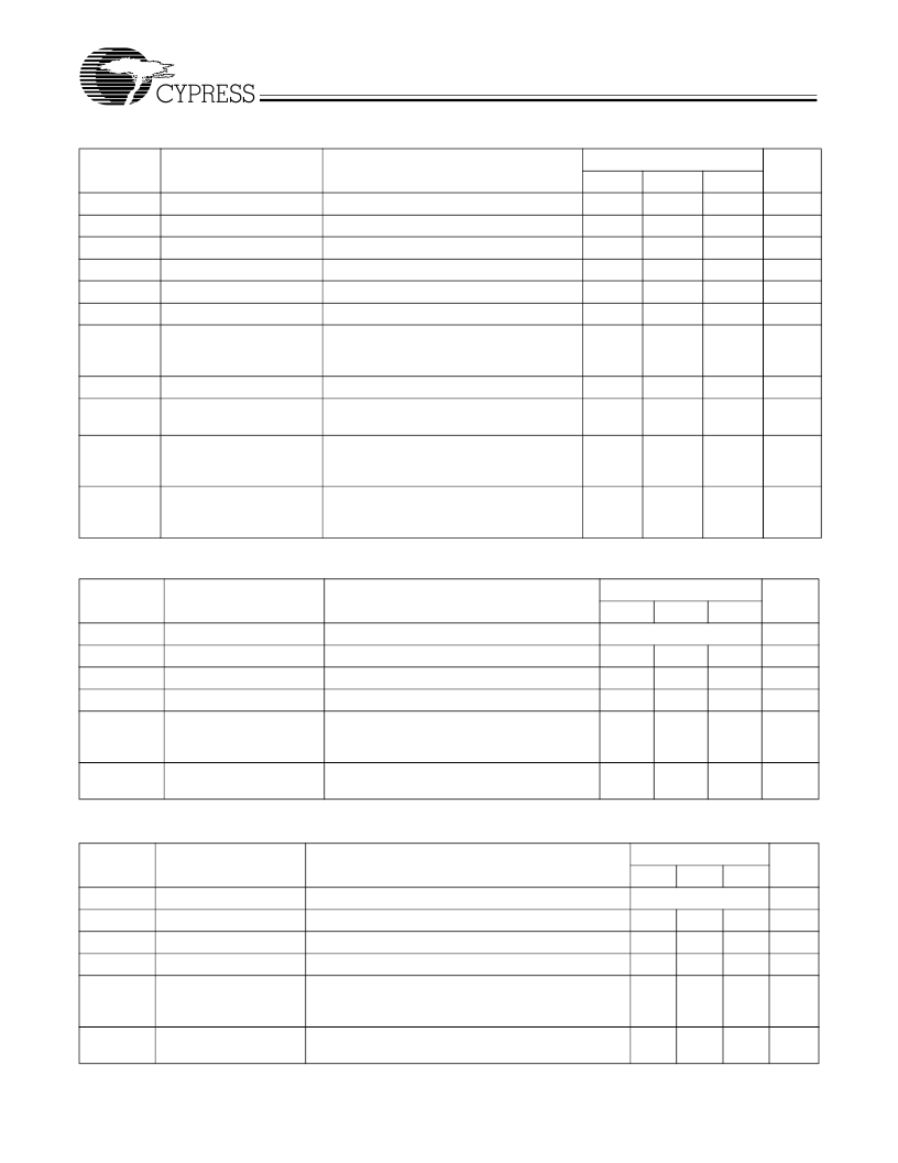
PCI Clock Outputs, PCI_F and PCI1:5 (Lump Capacitance Test Load = 30 pF)
Parameter
t
P
t
H
t
L
t
R
t
F
t
D
t
JC
Description
Test Condition/Comments
Measured on rising edge at 1.5V
CPU = 66.6/100 MHz
Unit
ns
Min.
30
Typ.
Max.
Period
High Time
Duration of clock cycle above 2.4V
12.0
ns
Low Time
Duration of clock cycle below 0.4V
12.0
ns
Output Rise Edge Rate
Measured from 0.4V to 2.4V
1
4
V/ns
Output Fall Edge Rate
Measured from 2.4V to 0.4V
1
4
V/ns
Duty Cycle
Measured on rising and falling edge at 1.5V
45
55
%
Jitter, Cycle-to-Cycle
Measured on rising edge at 1.5V. Maximum
difference of cycle time between two adja-
cent cycles.
250
ps
t
SK
t
O
Output Skew
Measured on rising edge at 1.5V
500
ps
CPU to PCI Clock Skew
Covers all CPU/PCI outputs. Measured on
rising edge at 1.5V. CPU leads PCI output.
1.5
4
ns
f
ST
Frequency Stabilization
from Power-up (cold start)
Assumes full supply voltage reached within
1 ms from power-up. Short cycles exist pri-
or to frequency stabilization.
3
ms
Z
o
AC Output Impedance
Average value during switching transition.
Used for determining series termination
value.
30
IOAPIC Clock Output (Lump Capacitance Test Load = 20 pF)
Parameter
Description
Test Condition/Comments
CPU = 66.6/100 MHz
Min.
Typ.
Unit
Max.
f
Frequency, Actual
Frequency generated by crystal oscillator
14.31818
MHz
t
R
t
F
t
D
f
ST
Output Rise Edge Rate
Measured from 0.4V to 2.0V
1
4
V/ns
Output Fall Edge Rate
Measured from 2.0V to 0.4V
1
4
V/ns
Duty Cycle
Measured on rising and falling edge at 1.25V
45
55
%
Frequency Stabilization
from Power-up (cold start)
Assumes full supply voltage reached within
1 ms from power-up. Short cycles exist prior
to frequency stabilization.
1.5
ms
Z
o
AC Output Impedance
Average value during switching transition.
Used for determining series termination value.
15
REF0:1 Clock Output (Lump Capacitance Test Load = 20 pF)
Parameter
f
Description
Frequency, Actual
Test Condition/Comments
Frequency generated by crystal oscillator
CPU = 66.6/100 MHz
Unit
MHz
Min.
Typ.
14.318
Max.
t
R
t
F
t
D
f
ST
Output Rise Edge Rate
Measured from 0.4V to 2.4V
0.5
2
V/ns
Output Fall Edge Rate
Measured from 2.4V to 0.4V
0.5
2
V/ns
Duty Cycle
Measured on rising and falling edge at 1.5V.
45
55
%
Frequency Stabilization
from Power-up (cold
start)
Assumes full supply voltage reached within 1 ms from
power-up. Short cycles exist prior to frequency stabili-
zation.
3
ms
Z
o
AC Output Impedance
Average value during switching transition. Used for de-
termining series termination value.
40
相关PDF资料 |
PDF描述 |
|---|---|
| W152-12X | Eight Distributed-Output Clock Driver |
| W152-1G | EIGHT DISTRIBUTED-OUTPUT CLOCK DRIVER|CMOS|SOP|16PIN|PLASTIC |
| W152-1X | Eight Distributed-Output Clock Driver |
| W152-2G | EIGHT DISTRIBUTED-OUTPUT CLOCK DRIVER|CMOS|SOP|16PIN|PLASTIC |
| W152-2X | Eight Distributed-Output Clock Driver |
相关代理商/技术参数 |
参数描述 |
|---|---|
| W149HT | 制造商:Cypress Semiconductor 功能描述: |
| W14B | 制造商:NSC 制造商全称:National Semiconductor 功能描述:14 Lead Ceramic Flatpack NS Package Number W14B |
| W14B20001-AZZ00-000 | 制造商:Carling Technologies 功能描述:W-SERIES ROCKER SWITCH - Bulk |
| W14B2GJJ1-A79XX-100-XBA1 | 制造商:Carling Technologies 功能描述:W-SERIES ROCKER SWITCH - Bulk |
| W14B2GJJ1-A79XX-100-XCS1 | 制造商:Carling Technologies 功能描述:W-SERIES ROCKER SWITCH - Bulk |
发布紧急采购,3分钟左右您将得到回复。