- 您现在的位置:买卖IC网 > PDF目录1971 > W83627UHG (Nuvoton Technology Corporation of America)IC I/O CONTROLLER 128-QFP PDF资料下载
参数资料
| 型号: | W83627UHG |
| 厂商: | Nuvoton Technology Corporation of America |
| 文件页数: | 101/240页 |
| 文件大小: | 0K |
| 描述: | IC I/O CONTROLLER 128-QFP |
| 标准包装: | 66 |
| 应用: | PC,PDA |
| 接口: | LPC |
| 电源电压: | 3.3V,5V |
| 封装/外壳: | 128-XFQFN |
| 供应商设备封装: | 128-QFP(14x20) |
| 包装: | 管件 |
| 安装类型: | 表面贴装 |
第1页第2页第3页第4页第5页第6页第7页第8页第9页第10页第11页第12页第13页第14页第15页第16页第17页第18页第19页第20页第21页第22页第23页第24页第25页第26页第27页第28页第29页第30页第31页第32页第33页第34页第35页第36页第37页第38页第39页第40页第41页第42页第43页第44页第45页第46页第47页第48页第49页第50页第51页第52页第53页第54页第55页第56页第57页第58页第59页第60页第61页第62页第63页第64页第65页第66页第67页第68页第69页第70页第71页第72页第73页第74页第75页第76页第77页第78页第79页第80页第81页第82页第83页第84页第85页第86页第87页第88页第89页第90页第91页第92页第93页第94页第95页第96页第97页第98页第99页第100页当前第101页第102页第103页第104页第105页第106页第107页第108页第109页第110页第111页第112页第113页第114页第115页第116页第117页第118页第119页第120页第121页第122页第123页第124页第125页第126页第127页第128页第129页第130页第131页第132页第133页第134页第135页第136页第137页第138页第139页第140页第141页第142页第143页第144页第145页第146页第147页第148页第149页第150页第151页第152页第153页第154页第155页第156页第157页第158页第159页第160页第161页第162页第163页第164页第165页第166页第167页第168页第169页第170页第171页第172页第173页第174页第175页第176页第177页第178页第179页第180页第181页第182页第183页第184页第185页第186页第187页第188页第189页第190页第191页第192页第193页第194页第195页第196页第197页第198页第199页第200页第201页第202页第203页第204页第205页第206页第207页第208页第209页第210页第211页第212页第213页第214页第215页第216页第217页第218页第219页第220页第221页第222页第223页第224页第225页第226页第227页第228页第229页第230页第231页第232页第233页第234页第235页第236页第237页第238页第239页第240页
W83627UHG
Publication Release Date: March 24, 2008
-4-
Revision 1.44
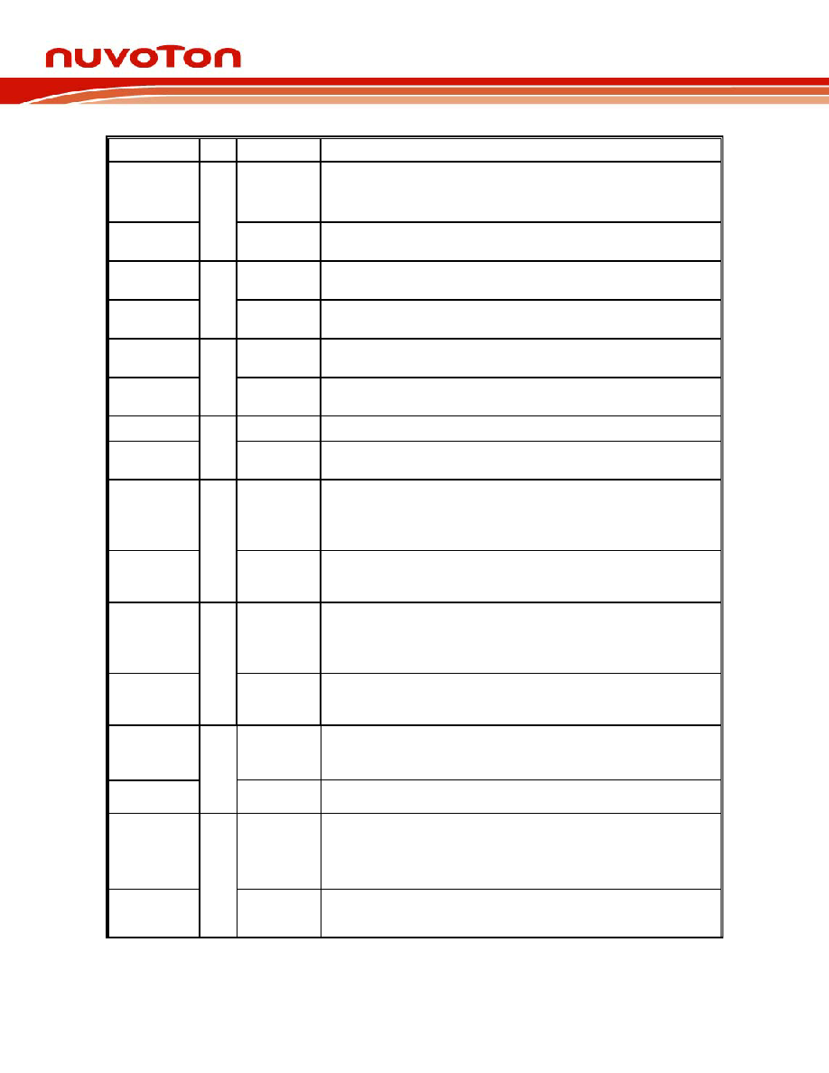
SYMBOL
PIN
I/O
DESCRIPTION
DIR#
OD
24
Direction of the head step motor. An open-drain output.
Logic 1 = outward motion
Logic 0 = inward motion
DTRF#
9
O
24
UART F Data Terminal Ready. An active low signal informs the
modem or data set that the controller is ready to communicate.
STEP#
OD
24
Step output pulses. This active-low open-drain output produces
a pulse to move the head to another track.
SINF
10
IN
t
Serial Input. This pin is used to receive serial data through the
communication link.
WD#
OD
24
Write data. This logic-low open-drain writes pre-compensation
serial data to the selected FDD. An open-drain output.
SOUTF
11
O
24
UART F Serial Output. This pin is used to transmit serial data
out to the communication link.
WE#
OD
24
Write enable. An open-drain output.
DCDF#
13
IN
t
Data Carrier Detect. An active low signal indicates the modem
or data set has detected a data carrier.
TRAK0#
IN
tsu
Track 0. This Schmitt-trigger input from the disk drive is active-
low when the head is positioned over the outermost track. This
input pin needs to connect a pulled-up 1-K
Ω resistor to 5V for
Floppy Drive compatibility.
GP63
14
I/OD
12ts
General purpose I/O port 6 bit 3.
WP#
IN
tsu
Write Protected. This active-low Schmitt input from the disk
drive indicates that the diskette is write-protected. This input pin
needs to connect a pulled-up 1-K
Ω resistor to 5V for Floppy
Drive compatibility.
GP62
15
I/OD
12ts
General purpose I/O port 6 bit 2.
RDATA#
IN
tsu
The read-data input signal from the FDD. This input pin needs to
connect a pulled-up 1-K
Ω resistor to 5V for Floppy Drive
compatibility.
GP61
16
I/OD
12ts
General purpose I/O port 6 bit 1.
HEAD#
OD
24
Head Select. This open-drain output determines which disk
drive head is active.
Logic 1 = side 0
Logic 0 = side 1
RIF#
17
IN
t
Ring Indicator. An active low signal indicates that a ring signal
is being received from the modem or data set.
相关PDF资料 |
PDF描述 |
|---|---|
| W83L951DG | IC EMBEDDED CNTRLR 128-LQFP |
| X90100M8IZT1 | IC DIGITAL CAPACITOR NV 8-MSOP |
| X9015WS8T1 | IC XDCP SGL 32-TAP 10K 8-SOIC |
| X9110TV14I-2.7 | IC XDCP SGL 1024TAP 100K 14TSSOP |
| X9111TV14I-2.7T1 | IC XDCP SGL 1024TAP 100K 14TSSOP |
相关代理商/技术参数 |
参数描述 |
|---|---|
| W83628AG | 制造商:Nuvoton Technology Corp 功能描述:PCI to ISA Bus Conversion 128-Pin QFP 制造商:Nuvoton Technology 功能描述:PCI to ISA Bus Conversion 128-Pin QFP |
| W83628F | 制造商:WINBOND 制造商全称:Winbond 功能描述:PCI TO ISA BRIDGE SET |
| W83629AG | 制造商:Nuvoton Technology Corp 功能描述:PCI to ISA Bus Conversion 48-Pin LQFP |
| W83629D | 制造商:WINBOND 制造商全称:Winbond 功能描述:PCI TO ISA BRIDGE SET |
| W83637HF | 制造商:WINBOND 制造商全称:Winbond 功能描述:LPC I/O |
发布紧急采购,3分钟左右您将得到回复。