参数资料
| 型号: | X1288V14I-2.7A |
| 厂商: | Intersil |
| 文件页数: | 17/27页 |
| 文件大小: | 0K |
| 描述: | IC RTC/CAL/CPU SUP EE 14-TSSOP |
| 标准包装: | 95 |
| 类型: | 时钟/日历 |
| 特点: | 警报器,闰年,监控器,监视计时器 |
| 时间格式: | HH:MM:SS:hh(12/24 小时) |
| 数据格式: | YY-MM-DD-dd |
| 接口: | I²C,2 线串口 |
| 电源电压: | 2.7 V ~ 5.5 V |
| 电压 - 电源,电池: | 1.8 V ~ 5.5 V |
| 工作温度: | -40°C ~ 85°C |
| 安装类型: | 表面贴装 |
| 封装/外壳: | 14-TSSOP(0.173",4.40mm 宽) |
| 供应商设备封装: | 14-TSSOP |
| 包装: | 管件 |
第1页第2页第3页第4页第5页第6页第7页第8页第9页第10页第11页第12页第13页第14页第15页第16页当前第17页第18页第19页第20页第21页第22页第23页第24页第25页第26页第27页
24
FN8102.3
April 14, 2006
from the X1 and X2 pins. Also, minimizing the switch-
ing current at this pin by careful selection of the pullup
resistor value will reduce noise. Intersil suggests a
minimum value of 5.1k for 32.768kHz, and higher val-
ues (i.e. 20k
) for lower frequency PHZ outputs.
For other RTC products, the same rules stated above
should be observed, but adjusted slightly since the
packages and pinouts are slightly different.
Assembly
Most electronic circuits do not have to deal with
assembly issues, but with the RTC devices assembly
includes insertion or soldering of a live battery into an
unpowered circuit. If a socket is soldered to the board,
and a battery is inserted in final assembly, then there
are no issues with operation of the RTC. If the battery
is soldered to the board directly, then the RTC device
Vback pin will see some transient upset from either
soldering tools or intermittent battery connections
which can stop the circuit from oscillating. Once the
battery is soldered to the board, the only way to assure
the circuit will start up is to momentarily (very short
period of time!) short the Vback pin to ground and the
circuit will begin to oscillate.
Oscillator Measurements
When a proper crystal is selected and the layout
guidelines above are observed, the oscillator should
start up in most circuits in less than one second. Some
circuits may take slightly longer, but startup should
definitely occur in less than 5 seconds. When testing
RTC circuits, the most common impulse is to apply a
scope probe to the circuit at the X2 pin (oscillator out-
put) and observe the waveform. DO NOT DO THIS!
Although in some cases you may see a useable wave-
form, due to the parasitics (usually 10pF to ground)
applied with the
scope probe, there will be no useful information in that
waveform other than the fact that the circuit is oscillat-
ing. The X2 output is sensitive to capacitive imped-
ance so the voltage levels and the frequency will be
affected by the parasitic elements in the scope probe.
Applying a scope probe can possibly cause a faulty
oscillator to start up, hiding other issues (although in
the Intersil RTC’s, the internal circuitry assures startup
when using the proper crystal and layout).
The best way to analyze the RTC circuit is to power it
up and read the real time clock as time advances, or if
the chip has the PHZ output, look at the output of that
pin on an oscilloscope (after enabling it with the con-
trol register). Alternatively, the
X1226/1286/1288
devices have an IRQ- output which can be checked by
setting an alarm for each minute. Using the pulse
interrupt mode setting, the once-per-minute interrupt
functions as an indication of proper oscillation.
Backup Battery Operation
Many types of batteries can be used with the Intersil
RTC products. 3.0V or 3.6V Lithium batteries are
appropriate, and sizes are available that can power a
Intersil RTC device for up to 10 years. Another option
is to use a supercapacitor for applications where Vcc
may disappear intermittently for short periods of time.
Depending on the value of supercapacitor used,
backup time can last from a few days to two weeks
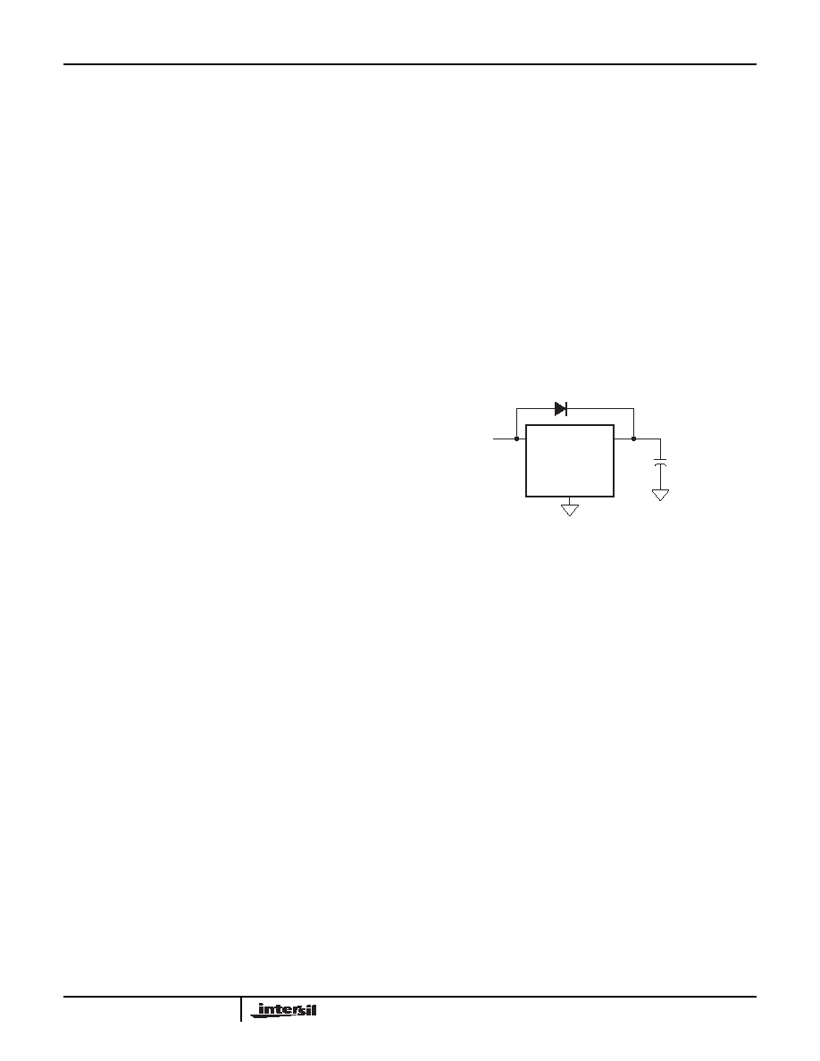
(with >1F). A simple silicon or Schottky barrier diode
can be used in series with Vcc to charge the superca-
pacitor, which is connected to the Vback pin. Do not
use the diode to charge a battery (especially lithium
batteries!).
Since the battery switchover occurs at Vcc=Vback-
0.1V (see Figure 20), the battery voltage must always
be lower than the Vcc voltage during normal operation
or the battery will be drained. A second consideration
is the trip point setting for the system RESET- func-
tion, known as Vtrip. Vtrip is set at the factory at levels
for systems with either Vcc = 5V or 3.3V operation,
with the following standard options:
VTRIP = 4.63V ± 3%
VTRIP = 4.38V ± 3%
VTRIP = 2.85V ± 3%
VTRIP = 2.65V ± 3%
2.7-5.5V
Supercapacitor
VSS
VCC
Vback
FIGURE 20. SUPERCAPACTOR CHARGING CIRCUIT
X1288
相关PDF资料 |
PDF描述 |
|---|---|
| MCP4161T-503E/MF | IC POT DGTL SNGL 50K SPI 8DFN |
| VE-B1M-MW-B1 | CONVERTER MOD DC/DC 10V 100W |
| X1288V14I-2.7 | IC RTC/CAL/CPU SUP EE 14-TSSOP |
| VE-21M-MW | CONVERTER MOD DC/DC 10V 100W |
| X1288V14I | IC RTC/CAL/CPU SUP EE 14-TSSOP |
相关代理商/技术参数 |
参数描述 |
|---|---|
| X1288V14I-4.5A | 功能描述:IC RTC/CAL/CPU SUP EE 14-TSSOP RoHS:否 类别:集成电路 (IC) >> 时钟/计时 - 实时时钟 系列:- 产品培训模块:Obsolescence Mitigation Program 标准包装:1 系列:- 类型:时钟/日历 特点:警报器,闰年,SRAM 存储容量:- 时间格式:HH:MM:SS(12/24 小时) 数据格式:YY-MM-DD-dd 接口:SPI 电源电压:2 V ~ 5.5 V 电压 - 电源,电池:- 工作温度:-40°C ~ 85°C 安装类型:表面贴装 封装/外壳:8-WDFN 裸露焊盘 供应商设备封装:8-TDFN EP 包装:管件 |
| X1288V14I-4.5AT1 | 功能描述:IC RTC/CAL/CPU SUP EE 14-TSSOP RoHS:否 类别:集成电路 (IC) >> 时钟/计时 - 实时时钟 系列:- 产品培训模块:Obsolescence Mitigation Program 标准包装:1 系列:- 类型:时钟/日历 特点:警报器,闰年,SRAM 存储容量:- 时间格式:HH:MM:SS(12/24 小时) 数据格式:YY-MM-DD-dd 接口:SPI 电源电压:2 V ~ 5.5 V 电压 - 电源,电池:- 工作温度:-40°C ~ 85°C 安装类型:表面贴装 封装/外壳:8-WDFN 裸露焊盘 供应商设备封装:8-TDFN EP 包装:管件 |
| X1288V14IT1 | 功能描述:IC RTC/CAL/CPU SUP EE 14-TSSOP RoHS:否 类别:集成电路 (IC) >> 时钟/计时 - 实时时钟 系列:- 产品培训模块:Obsolescence Mitigation Program 标准包装:1 系列:- 类型:时钟/日历 特点:警报器,闰年,SRAM 存储容量:- 时间格式:HH:MM:SS(12/24 小时) 数据格式:YY-MM-DD-dd 接口:SPI 电源电压:2 V ~ 5.5 V 电压 - 电源,电池:- 工作温度:-40°C ~ 85°C 安装类型:表面贴装 封装/外壳:8-WDFN 裸露焊盘 供应商设备封装:8-TDFN EP 包装:管件 |
| X1288V14IZ | 制造商:Rochester Electronics LLC 功能描述: 制造商:Intersil Corporation 功能描述: |
| X1288V14IZ-2.7 | 制造商:INTERSIL 制造商全称:Intersil Corporation 功能描述:2-Wire⑩ RTC Real Time Clock/Calendar/CPU Supervisor with EEPROM |
发布紧急采购,3分钟左右您将得到回复。