参数资料
| 型号: | XC2S200E-6PQ208C |
| 厂商: | Xilinx Inc |
| 文件页数: | 22/108页 |
| 文件大小: | 0K |
| 描述: | IC FPGA 1.8V 1176 CLB'S 208-PQFP |
| 标准包装: | 24 |
| 系列: | Spartan®-IIE |
| LAB/CLB数: | 1176 |
| 逻辑元件/单元数: | 5292 |
| RAM 位总计: | 57344 |
| 输入/输出数: | 146 |
| 门数: | 200000 |
| 电源电压: | 1.71 V ~ 1.89 V |
| 安装类型: | 表面贴装 |
| 工作温度: | 0°C ~ 85°C |
| 封装/外壳: | 208-BFQFP |
| 供应商设备封装: | 208-PQFP(28x28) |
| 其它名称: | 122-1209 |
第1页第2页第3页第4页第5页第6页第7页第8页第9页第10页第11页第12页第13页第14页第15页第16页第17页第18页第19页第20页第21页当前第22页第23页第24页第25页第26页第27页第28页第29页第30页第31页第32页第33页第34页第35页第36页第37页第38页第39页第40页第41页第42页第43页第44页第45页第46页第47页第48页第49页第50页第51页第52页第53页第54页第55页第56页第57页第58页第59页第60页第61页第62页第63页第64页第65页第66页第67页第68页第69页第70页第71页第72页第73页第74页第75页第76页第77页第78页第79页第80页第81页第82页第83页第84页第85页第86页第87页第88页第89页第90页第91页第92页第93页第94页第95页第96页第97页第98页第99页第100页第101页第102页第103页第104页第105页第106页第107页第108页

20
DS077-2 (v3.0) August 9, 2013
Product Specification
Spartan-IIE FPGA Family: Functional Description
R
— OBSOLETE — OBSOLETE — OBSOLETE — OBSOLETE —
Bit Sequence
The bit sequence within each IOB is: In, Out, 3-State. The
input-only pins contribute only the In bit to the boundary
scan I/O data register, while the output-only pins contributes
all three bits.
From a cavity-up view of the chip (as shown in the FPGA
Editor), starting in the upper right chip corner, the boundary
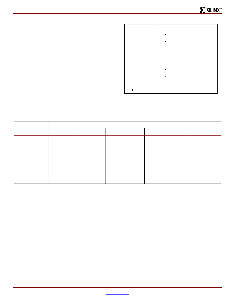
scan data-register bits are ordered as shown in Figure 15.
BSDL (Boundary Scan Description Language) files for
Spartan-IIE family devices are available on the Xilinx web
site.
Spartan-IIE FPGA boundary scan IDCODE values are
shown in Table 9.
Development System
Spartan-IIE FPGAs are supported by the Xilinx ISE CAE
tools. The basic methodology for Spartan-IIE FPGA design
consists of three interrelated steps: design entry, imple-
mentation, and verification. Industry-standard tools are
used for design entry and simulation, while Xilinx provides
proprietary architecture-specific tools for implementation.
The Xilinx development system is integrated under the
Xilinx Project Navigator software, providing designers with a
common user interface regardless of their choice of entry
and verification tools. The software simplifies the selection
of implementation options with pull-down menus and on-line
help.
Several advanced software features facilitate Spartan-IIE
FPGA design. CORE Generator tool functions, for exam-
ple, include macros with relative location constraints to
guide their placement. They help ensure optimal implemen-
tation of common functions.
For HDL design entry, the Xilinx FPGA development system
provides interfaces to several synthesis design environ-
ments.
A standard interface-file specification, Electronic Design
Interchange Format (EDIF), simplifies file transfers into and
out of the development system.
Spartan-IIE FPGAs are supported by a unified library of
standard functions. This library contains over 400 primitives
and macros, ranging from 2-input AND gates to 16-bit accu-
mulators, and includes arithmetic functions, comparators,
counters, data registers, decoders, encoders, I/O functions,
latches, Boolean functions, multiplexers, shift registers, and
barrel shifters.
The design environment supports hierarchical design entry,
with high-level designs that comprise major functional
blocks, while lower-level designs define the logic in these
blocks. These hierarchical design elements are automati-
cally combined by the implementation tools. Different
design entry tools can be combined within a hierarchical
Figure 15: Boundary Scan Bit Sequence
Bit 0 ( TDO end)
Bit 1
Bit 2
TDO.T
TDO.O
Top-edge IOBs (Right to Left)
Left-edge IOBs (Top to Bottom)
MODE.I
Bottom-edge IOBs (Left to Right)
Right-edge IOBs (Bottom to Top)
BSCANT.UPD
(TDI end)
DS001_10_032300
Table 9: Spartan-IIE IDCODE Values
Device
IDCODE
Version
Family
Array Size
Manufacturer
Required
XC2S50E
XXXX
0000 101
0 0001 0000
0000 1001 001
1
XC2S100E
XXXX
0000 101
0 0001 0100
0000 1001 001
1
XC2S150E
XXXX
0000 101
0 0001 1000
0000 1001 001
1
XC2S200E
XXXX
0000 101
0 0001 1100
0000 1001 001
1
XC2S300E
XXXX
0000 101
0 0010 0000
0000 1001 001
1
XC2S400E
XXXX
0000 101
0 0010 1000
0000 1001 001
1
XC2S600E
XXXX
0000 101
0 0011 0000
0000 1001 001
1
相关PDF资料 |
PDF描述 |
|---|---|
| 747275-4 | CONN D-SUB STRAIN RELIEF 9POS |
| XC3S700A-5FTG256C | IC FPGA SPARTAN-3A 256K 256FTBGA |
| XA3S400-4PQG208Q | IC FPGA SPARTAN-3 400K 208-PQFP |
| EEC43DTEF | CONN EDGECARD 86POS .100 EYELET |
| 229910-1 | CONN CABLE CLAMP BLACK .350-.425 |
相关代理商/技术参数 |
参数描述 |
|---|---|
| XC2S200E-6PQ208I | 功能描述:IC FPGA 1.8V 1176 CLB'S 208-PQFP RoHS:是 类别:集成电路 (IC) >> 嵌入式 - FPGA(现场可编程门阵列) 系列:Spartan®-IIE 标准包装:40 系列:Spartan® 6 LX LAB/CLB数:3411 逻辑元件/单元数:43661 RAM 位总计:2138112 输入/输出数:358 门数:- 电源电压:1.14 V ~ 1.26 V 安装类型:表面贴装 工作温度:-40°C ~ 100°C 封装/外壳:676-BGA 供应商设备封装:676-FBGA(27x27) |
| XC2S200E-6PQG208C | 功能描述:IC SPARTAN-IIE FPGA 200K 208PQFP RoHS:是 类别:集成电路 (IC) >> 嵌入式 - FPGA(现场可编程门阵列) 系列:Spartan®-IIE 标准包装:40 系列:Spartan® 6 LX LAB/CLB数:3411 逻辑元件/单元数:43661 RAM 位总计:2138112 输入/输出数:358 门数:- 电源电压:1.14 V ~ 1.26 V 安装类型:表面贴装 工作温度:-40°C ~ 100°C 封装/外壳:676-BGA 供应商设备封装:676-FBGA(27x27) |
| XC2S200E-6PQG208I | 制造商:XILINX 制造商全称:XILINX 功能描述:Spartan-IIE FPGA |
| XC2S200E-6TQ144C | 制造商:XILINX 制造商全称:XILINX 功能描述:Spartan-IIE 1.8V FPGA Family |
| XC2S200E-6TQ144I | 制造商:XILINX 制造商全称:XILINX 功能描述:Spartan-IIE 1.8V FPGA Family |
发布紧急采购,3分钟左右您将得到回复。