参数资料
| 型号: | XC3090A-7PC84C |
| 厂商: | Xilinx Inc |
| 文件页数: | 9/76页 |
| 文件大小: | 0K |
| 描述: | IC LOGIC CL ARRAY 9000GAT 84PLCC |
| 产品变化通告: | Product Discontinuation 27/Apr/2010 |
| 标准包装: | 1 |
| 系列: | XC3000A/L |
| LAB/CLB数: | 320 |
| RAM 位总计: | 64160 |
| 输入/输出数: | 70 |
| 门数: | 6000 |
| 电源电压: | 4.75 V ~ 5.25 V |
| 安装类型: | 表面贴装 |
| 工作温度: | 0°C ~ 85°C |
| 封装/外壳: | 84-LCC(J 形引线) |
| 供应商设备封装: | 84-PLCC |
| 其它名称: | 122-1034 XC3090A-7PC84C-ND |
第1页第2页第3页第4页第5页第6页第7页第8页当前第9页第10页第11页第12页第13页第14页第15页第16页第17页第18页第19页第20页第21页第22页第23页第24页第25页第26页第27页第28页第29页第30页第31页第32页第33页第34页第35页第36页第37页第38页第39页第40页第41页第42页第43页第44页第45页第46页第47页第48页第49页第50页第51页第52页第53页第54页第55页第56页第57页第58页第59页第60页第61页第62页第63页第64页第65页第66页第67页第68页第69页第70页第71页第72页第73页第74页第75页第76页
R
November 9, 1998 (Version 3.1)
7-19
XC3000 Series Field Programmable Gate Arrays
7
Configuration
Initialization Phase
An internal power-on-reset circuit is triggered when power
is applied. When VCC reaches the voltage at which portions
of the FPGA device begin to operate (nominally 2.5 to 3 V),
the programmable I/O output buffers are 3-stated and a
high-impedance pull-up resistor is provided for the user
I/O pins. A time-out delay is initiated to allow the power
supply voltage to stabilize. During this time the power-down
mode is inhibited. The Initialization state time-out (about 11
to 33 ms) is determined by a 14-bit counter driven by a
self-generated internal timer. This nominal 1-MHz timer is
subject to variations with process, temperature and power
supply. As shown in Table 1, five configuration mode
choices are available as determined by the input levels of
three mode pins; M0, M1 and M2.
In Master configuration modes, the device becomes the
source of the Configuration Clock (CCLK). The beginning
of configuration of devices using Peripheral or Slave
modes must be delayed long enough for their initialization
to be completed. An FPGA with mode lines selecting a
Master configuration mode extends its initialization state
using four times the delay (43 to 130 ms) to assure that all
daisy-chained slave devices, which it may be driving, will
be ready even if the master is very fast, and the slave(s)
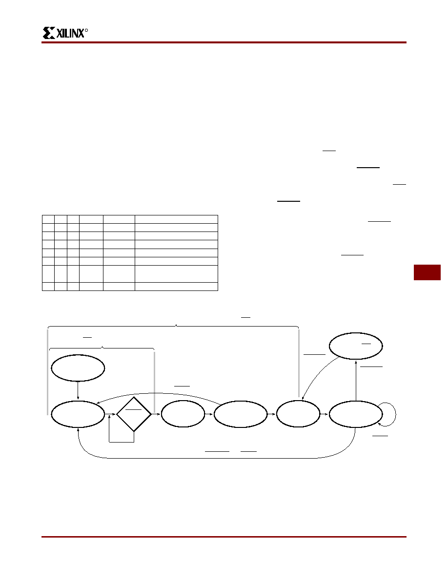
very slow. Figure 20 shows the state sequences. At the end
of Initialization, the device enters the Clear state where it
clears
the
configuration
memory.
The
active
Low,
open-drain initialization signal INIT indicates when the Ini-
tialization and Clear states are complete. The FPGA tests
for the absence of an external active Low RESET before it
makes a final sample of the mode lines and enters the Con-
figuration state. An external wired-AND of one or more INIT
pins can be used to control configuration by the assertion of
the active-Low RESET of a master mode device or to sig-
nal a processor that the FPGAs are not yet initialized.
If a configuration has begun, a re-assertion of RESET for a
minimum of three internal timer cycles will be recognized
and the FPGA will initiate an abort, returning to the Clear
state to clear the partially loaded configuration memory
words. The FPGA will then resample RESET and the mode
lines before re-entering the Configuration state.
During configuration, the XC3000A, XC3000L, XC3100A,
and XC3100L devices check the bit-stream format for stop
bits in the appropriate positions. Any error terminates the
configuration and pulls INIT Low.
Table 1: Configuration Mode Choices
M0 M1 M2
CCLK
Mode
Data
0
output
Master
Bit Serial
0
1
output
Master
Byte Wide Addr. = 0000 up
010
—
reserved
—
0
1
output
Master
Byte Wide Addr. = FFFF down
1
0
—
reserved
—
1
0
1
output
Peripheral Byte Wide
1
0
—
reserved
—
1
input
Slave
Bit Serial
All User I/O Pins 3-Stated with High Impedance Pull-Up, HDC=High, LDC=Low
Initialization
Power-On
Time Delay
Clear
Configuration
Memory
Test
Mode Pins
Configuration
Program Mode
Start-Up
Operational
Mode
Power Down
No HDC, LDC
or Pull-Up
No
X3399
INIT Output = Low
Clear Is
~ 200 Cycles for the XC3020A—130 to 400
s
~ 250 Cycles for the XC3030A—165 to 500
s
~ 290 Cycles for the XC3042A—195 to 580
s
~ 330 Cycles for the XC3064A—220 to 660
s
~ 375 Cycles for the XC3090A—250 to 750
s
RESET
Active
PWRDWN
Inactive
PWRDWN
Active
Active RESET
Operates on
User Logic
Low on DONE/PROGRAM and RESET
Active RESET
Power-On Delay is
214 Cycles for Non-Master Mode—11 to 33 ms
216 Cycles for Master Mode—43 to 130 ms
Figure 20: A State Diagram of the Configuration Process for Power-up and Reprogram.
Product Obsolete or Under Obsolescence
相关PDF资料 |
PDF描述 |
|---|---|
| XC3064A-7PC84C | IC LOGIC CL ARRAY 6400GAT 84PLCC |
| XC3064A-7PQ160C | IC LOGIC CL ARRAY 6400GAT 160PQF |
| ASC49DRYH-S93 | CONN EDGECARD 98POS DIP .100 SLD |
| AMC44DRTI-S13 | CONN EDGECARD 88POS .100 EXTEND |
| AMC44DREI-S13 | CONN EDGECARD 88POS .100 EXTEND |
相关代理商/技术参数 |
参数描述 |
|---|---|
| XC3090A-7PC84C0090 | 制造商:Xilinx 功能描述: |
| XC3090A7PC84I | 制造商:XIL 功能描述:3090A7PC XILINX'95 |
| XC3090A-7PC84I | 制造商:XIL 功能描述:3090A7PC XILINX'95 制造商:Xilinx 功能描述: |
| XC3090A-7PC84I0100 | 制造商:Xilinx 功能描述: |
| XC3090A-7PG175C | 制造商:XILINX 制造商全称:XILINX 功能描述:Field Programmable Gate Arrays (XC3000A/L, XC3100A/L) |
发布紧急采购,3分钟左右您将得到回复。