- 您现在的位置:买卖IC网 > PDF目录16821 > XR17V358IB-E4-EVB (Exar Corporation)EVAL BOARD FOR XR17V358-E4 PDF资料下载
参数资料
| 型号: | XR17V358IB-E4-EVB |
| 厂商: | Exar Corporation |
| 文件页数: | 47/68页 |
| 文件大小: | 0K |
| 描述: | EVAL BOARD FOR XR17V358-E4 |
| 产品培训模块: | PCIe UARTs UART Product Overview |
| 标准包装: | 1 |
| 主要目的: | 接口,UART |
| 嵌入式: | 否 |
| 已用 IC / 零件: | XR17V358 |
| 已供物品: | 板 |
| 相关产品: | 1016-1294-ND - IC UART PCIE OCTAL 176FPBGA |
| 其它名称: | 1016-1295 |
第1页第2页第3页第4页第5页第6页第7页第8页第9页第10页第11页第12页第13页第14页第15页第16页第17页第18页第19页第20页第21页第22页第23页第24页第25页第26页第27页第28页第29页第30页第31页第32页第33页第34页第35页第36页第37页第38页第39页第40页第41页第42页第43页第44页第45页第46页当前第47页第48页第49页第50页第51页第52页第53页第54页第55页第56页第57页第58页第59页第60页第61页第62页第63页第64页第65页第66页第67页第68页
XR17V358
51
REV. 1.0.4
HIGH PERFORMANCE OCTAL PCI EXPRESS UART
Wake-up indicator is cleared by a read to the INT0 register.
]
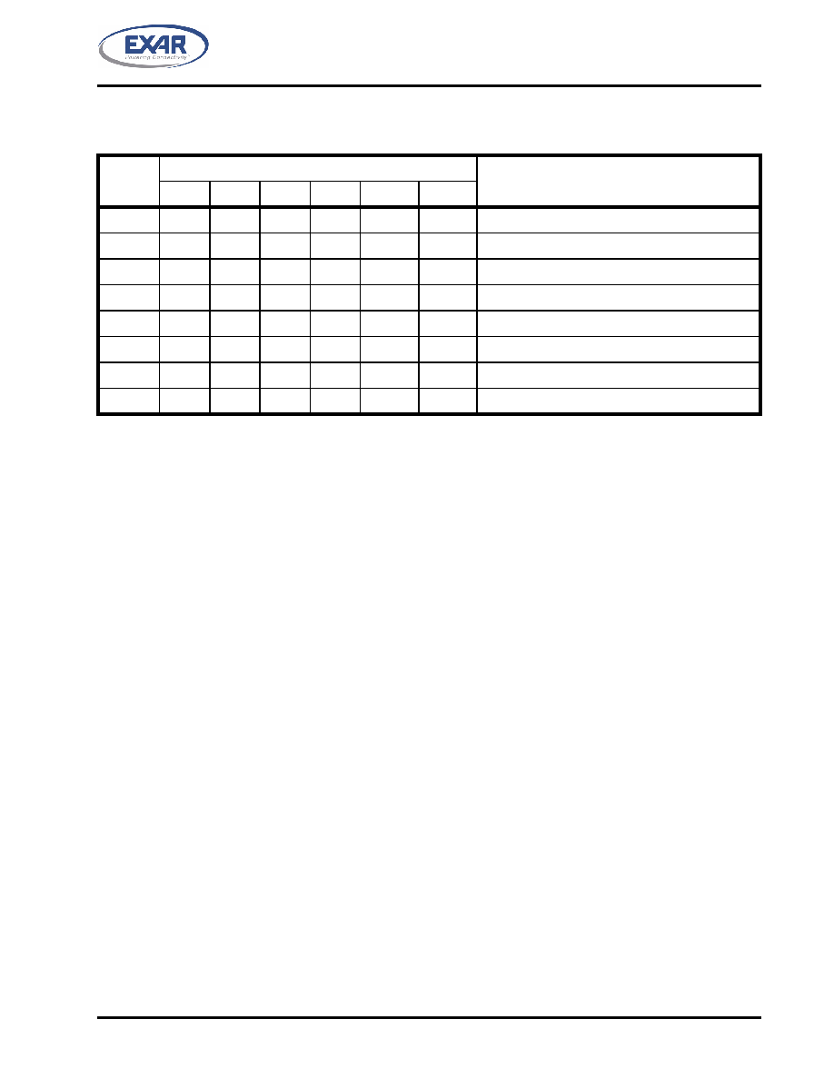
TABLE 15: INTERRUPT SOURCE AND PRIORITY LEVEL
PRIORITY
ISR REGISTER STATUS BITS
SOURCE OF THE INTERRUPT
LEVEL
BIT [5]
BIT [4]
BIT [3]
BIT [2]
BIT [1]
BIT [0]
1
0
1
0
LSR (Receiver Line Status Register)
2
0
1
0
RXRDY (Received Data Ready)
3
0
1
0
RXRDY (Receive Data Time-out)
4
0
1
0
TXRDY (Transmitter Holding Register Empty)
5
0
MSR (Modem Status Register)
6
0
1
0
RXRDY (Received Xon/Xoff or Special character)
7
1
0
CTS#/DSR#, RTS#/DTR# change of state
X
0
1
None (default)
ISR[7:6]: FIFO Enable Status
These bits are set to a logic 0 when the FIFOs are disabled. They are set to a logic 1 when the FIFOs are
enabled.
ISR[5:1]: Interrupt Status
These bits indicate the source for a pending interrupt at interrupt priority levels (See Table 15). See “Section
4.5.1, Interrupt Generation:” on page 50 and “Section 4.5.2, Interrupt Clearing:” on page 50 for details.
ISR[0]: Interrupt Status
Logic 0 = An interrupt is pending and the ISR contents may be used as a pointer to the appropriate interrupt
service routine.
Logic 1 = No interrupt pending. (default condition)
4.6
FIFO Control Register (FCR) - Write Only
This register is used to enable the FIFOs, clear the FIFOs, set the transmit/receive FIFO trigger levels, and
select the DMA mode. The DMA, and FIFO modes are defined as follows:
FCR[7:6]: Receive FIFO Trigger Select
(logic 0 = default, RX trigger level =1)
The FCTR bits [5:4] are associated with these 2 bits. These 2 bits are used to set the trigger level for the
receive FIFO. The UART will issue a receive interrupt when the number of the characters in the FIFO crosses
the trigger level. Table 16 shows the complete selections. Note that the receiver and the transmitter cannot use
different trigger tables. Whichever selection is made last applies to both the RX and TX side.
FCR[5:4]: Transmit FIFO Trigger Select (requires EFR bit [4]=1)
(logic 0 = default, TX trigger level = 1)
The FCTR bits [7:6] are associated with these 2 bits by selecting one of the four tables. The 4 user selectable
trigger levels in 4 tables are supported for compatibility reasons. These 2 bits set the trigger level for the
transmit FIFO interrupt. The UART will issue a transmit interrupt when the number of characters in the FIFO
falls below the selected trigger level, or when it gets empty in case that the FIFO did not get filled over the
trigger level on last re-load. Table 16 below shows the selections.
相关PDF资料 |
PDF描述 |
|---|---|
| ECA10DTKT-S288 | CONN EDGECARD 20POS .125 EXTEND |
| H0PPS-2406G | DIP CABLE - HDP24S/AE24G/HDP24S |
| EBM25DRMH | CONN EDGECARD 50POS .156 WW |
| HCM08DSEI-S243 | CONN EDGECARD 16POS .156 EYELET |
| HMM06DRYH-S13 | CONN EDGECARD 12POS .156 EXTEND |
相关代理商/技术参数 |
参数描述 |
|---|---|
| XR17V358IB-E8-EVB | 功能描述:界面开发工具 Eval Board for XR17V358IB-E8 RoHS:否 制造商:Bourns 产品:Evaluation Boards 类型:RS-485 工具用于评估:ADM3485E 接口类型:RS-485 工作电源电压:3.3 V |
| XR1857SN | 制造商:Electro-Term/Hollingsworth 功能描述: |
| XR1858SN | 制造商:Electro-Term/Hollingsworth 功能描述: |
| XR1859SN | 制造商:Electro-Term/Hollingsworth 功能描述: |
| XR1859SNT | 制造商:Hollingsworth 功能描述: |
发布紧急采购,3分钟左右您将得到回复。