参数资料
| 型号: | XRT5997IV-F |
| 厂商: | Exar Corporation |
| 文件页数: | 21/37页 |
| 文件大小: | 0K |
| 描述: | IC LIU E1 7CH 3.3V 100TQFP |
| 标准包装: | 90 |
| 类型: | 线路接口装置(LIU) |
| 驱动器/接收器数: | 7/7 |
| 规程: | E1 |
| 电源电压: | 3.14 V ~ 3.47 V |
| 安装类型: | 表面贴装 |
| 封装/外壳: | 100-LQFP |
| 供应商设备封装: | 100-TQFP(14x14) |
| 包装: | 托盘 |
第1页第2页第3页第4页第5页第6页第7页第8页第9页第10页第11页第12页第13页第14页第15页第16页第17页第18页第19页第20页当前第21页第22页第23页第24页第25页第26页第27页第28页第29页第30页第31页第32页第33页第34页第35页第36页第37页
XRT5997
28
Rev. 1.0.0
2.3
The “Peak Detector and Slicer Block
After the incoming line signal has passed through the
Receive Equalizer block, it will next be routed to the
“Slicer” block. The purpose of the “Slicer” block is to
quantify a given bit-period (or symbol) within the incom-
ing line signal as either a “1” or a “0”.
2.3
The “LOS Detector” block
The LOS Detector block, within each channel (of the
XRT5997 device) was specifically designed to comply
with the “LOS Declaration/Clearance” requirements per
ITU-T G.775. As a consequence, the channel will
declare an LOS Condition, (by driving the “RxLOS”
output pin “high”) if the received line signal amplitude
drops to –20dB or below. Further, the channel will clear
the LOS Condition if the signal amplitude rises back up
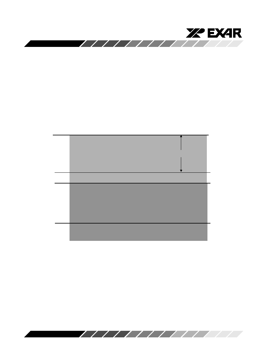
to –15dB or above. Figure 10 presents an illustration
that depicts the signal levels at which a given channel
(within the XRT5997 device) will assert and clear LOS.
0 dB
-6 dB
-9dB
-35dB
Maximum Cable Loss for E1
LOS Signal Must be Declared
LOS Signal Must be Cleared
LOS Signal may be Cleared or Declared
Figure 10. Illustration of the Signal Levels that the Receiver Sections
(within XRT5997 device) will declare and clear LOS
Timing Requirements associated with Declaring and
Clearing the LOS Indicator. The XRT5997 device was
designed to meet the ITU-T G.775 specification timing
requirements for declaring and clearing the LOS indica-
tor. In particular, the XRT5997 device will declare an
LOS, between 10 and 255 UI (or E1 bit-periods) after
the actual time the LOS condition occurred. Further,
the XRT5997 device will clear the LOS indicator within
10 to 255 UI after restoration of the incoming line
signal. Figure 11 illustrates the LOS Declaration and
Clearance behavior, in response to first, the “Loss of
Signal” event and then afterwards, the restoration of
the signal.
相关PDF资料 |
PDF描述 |
|---|---|
| XRT6164AIP-F | IC TXRX DGTL INTERFACE 16PDIP |
| XRT6164CD-F | IC TXRX DGTL INTERFACE 16SOIC |
| XRT6165ID-F | IC DGTL DATA PROCESSOR 24SOIC |
| XRT6166CD-F | IC DGTL DATA PROCESSOR 28SOIC |
| XRT7295AEIW-F | IC E3 LINE RECEIVER 20SOJ |
相关代理商/技术参数 |
参数描述 |
|---|---|
| XRT5997IVTR-F | 功能描述:外围驱动器与原件 - PCI 7 Ch. E1 LIU RoHS:否 制造商:PLX Technology 工作电源电压: 最大工作温度: 安装风格:SMD/SMT 封装 / 箱体:FCBGA-1156 封装:Tray |
| XRT59L81IG-F | 功能描述:时钟发生器及支持产品 BITS Clock Generator RoHS:否 制造商:Silicon Labs 类型:Clock Generators 最大输入频率:14.318 MHz 最大输出频率:166 MHz 输出端数量:16 占空比 - 最大:55 % 工作电源电压:3.3 V 工作电源电流:1 mA 最大工作温度:+ 85 C 安装风格:SMD/SMT 封装 / 箱体:QFN-56 |
| XRT59L81IGTR-F | 功能描述:时钟发生器及支持产品 BITS Clock Generator RoHS:否 制造商:Silicon Labs 类型:Clock Generators 最大输入频率:14.318 MHz 最大输出频率:166 MHz 输出端数量:16 占空比 - 最大:55 % 工作电源电压:3.3 V 工作电源电流:1 mA 最大工作温度:+ 85 C 安装风格:SMD/SMT 封装 / 箱体:QFN-56 |
| XRT59L91 | 制造商:EXAR 制造商全称:EXAR 功能描述:Single-Chip E1 Line Interface Unit |
| XRT59L91ES | 功能描述:外围驱动器与原件 - PCI 1 CH E1 AFE RoHS:否 制造商:PLX Technology 工作电源电压: 最大工作温度: 安装风格:SMD/SMT 封装 / 箱体:FCBGA-1156 封装:Tray |
发布紧急采购,3分钟左右您将得到回复。