参数资料
| 型号: | XRT75R12IB-L |
| 厂商: | Exar Corporation |
| 文件页数: | 63/90页 |
| 文件大小: | 0K |
| 描述: | IC LIU E3/DS3/STS-1 12CH 420TBGA |
| 标准包装: | 40 |
| 类型: | 线路接口装置(LIU) |
| 驱动器/接收器数: | 12/12 |
| 规程: | DS3,E3,STS-1 |
| 电源电压: | 3.135 V ~ 3.465 V |
| 安装类型: | 表面贴装 |
| 封装/外壳: | 420-LBGA 裸露焊盘 |
| 供应商设备封装: | 420-TBGA(35x35) |
| 包装: | 托盘 |
第1页第2页第3页第4页第5页第6页第7页第8页第9页第10页第11页第12页第13页第14页第15页第16页第17页第18页第19页第20页第21页第22页第23页第24页第25页第26页第27页第28页第29页第30页第31页第32页第33页第34页第35页第36页第37页第38页第39页第40页第41页第42页第43页第44页第45页第46页第47页第48页第49页第50页第51页第52页第53页第54页第55页第56页第57页第58页第59页第60页第61页第62页当前第63页第64页第65页第66页第67页第68页第69页第70页第71页第72页第73页第74页第75页第76页第77页第78页第79页第80页第81页第82页第83页第84页第85页第86页第87页第88页第89页第90页
XRT75R12
63
TWELVE CHANNEL E3/DS3/STS-1 LINE INTERFACE UNIT WITH JITTER ATTENUATOR
REV. 1.0.4
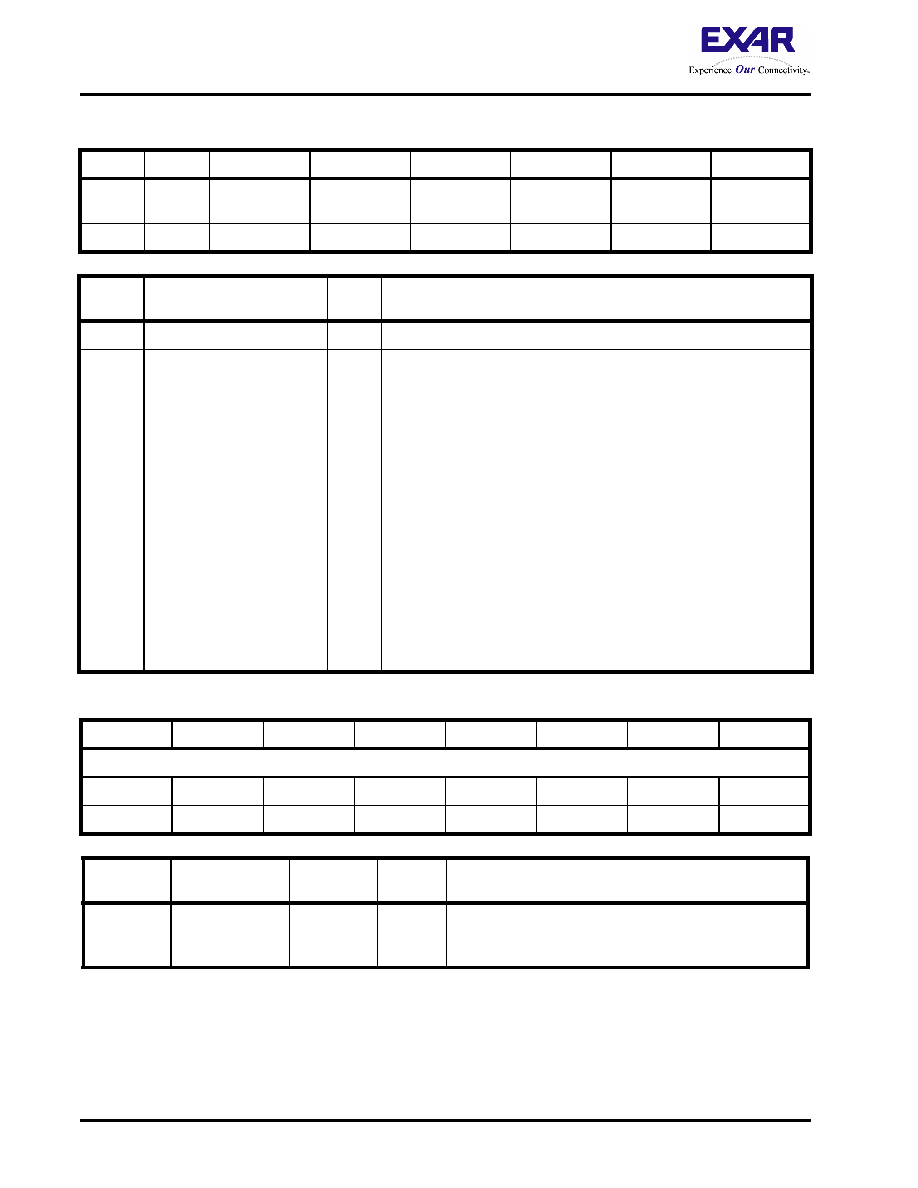
TABLE 26: CHANNEL LEVEL INTERRUPT STATUS REGISTER - CR225 (ADDRESS LOCATION = 0XE1)
BIT 7
BIT 6
BIT 5
BIT 4
BIT 3
BIT 2
BIT 1
BIT 0
Reserved Reserved
Channel 11
Interrupt Status
Channel 10
Interrupt Status
Channel 9
Interrupt Status
Channel 8
Interrupt Status
Channel 7
Interrupt Status
Channel 6
Interrupt Status
R/O
BIT
NUMBER
NAME
TYPE
DESCRIPTION
7, 6
Reserved
5
4
3
2
1
0
Channel 11 Interrupt Status
Channel 10 Interrupt Status
Channel 9 Interrupt Status
Channel 8 Interrupt Status
Channel 7 Interrupt Status
Channel 6 Interrupt Status
R/O
Channel n Interrupt Status Bit:
This READ-ONLY bit-field indicates whether the XRT75R12 has a
pending Channel n-related interrupt that is awaiting service. The last
six channels are serviced through this location and the other six at
address 0x61. These two registers are used by the Host to identify the
source channel of an active interrupt.
0 - Indicates that there is NO Channel n-related Interrupt awaiting ser-
vice.
1 - Indicates that there is at least one Channel n-related Interrupt await-
ing service. In this case, the user's Interrupt Service routine should be
written such that the Microprocessor will now proceed to read out the
contents of the Source Level Interrupt Status Register - Channel n
(Address Locations = 0xn2) to determine the exact source of the inter-
rupt request.
NOTE: Once this bit-field is set to "1", it will not be cleared back to "0"
until the user has read out the contents of the Source-Level
Interrupt Status Register bit, that corresponds to the interrupt
request channel.
TABLE 27: DEVICE/PART NUMBER REGISTER - CR110 (ADDRESS LOCATION = 0X6E)
BIT 7
BIT 6
BIT 5
BIT 4
BIT 3
BIT 2
BIT 1
BIT 0
Part Number ID Value
R/O
0
1
0
BIT NUMBER
NAME
TYPE
DEFAULT
VALUE
DESCRIPTION
7 - 0
Part Number ID
Value
R/O
0x78
Part Number ID Value:
This READ-ONLY register contains a unique value for the
XRT75R12. This value will always be 0x78.
相关PDF资料 |
PDF描述 |
|---|---|
| XRT75VL00DIV | IC LIU E3/DS3/STS-1 1CH 52TQFP |
| XRT75VL00IV-F | IC LIU E3/DS3/STS-1 1CH 52TQFP |
| XRT79L71IB-F | IC LIU/FRAMER DS3/E3 1CH 208BGA |
| XRT81L27IV-F | IC LIU EI 7CH 3.3V 128TQFP |
| XRT82D20IW-F | IC LIU E1 SGL 28SOJ |
相关代理商/技术参数 |
参数描述 |
|---|---|
| XRT75VL00 | 制造商:EXAR 制造商全称:EXAR 功能描述:E3/DS3/STS-1 LINE INTERFACE UNIT WITH JITTER ATTENUATOR |
| XRT75VL00_08 | 制造商:EXAR 制造商全称:EXAR 功能描述:E3/DS3/STS-1 LINE INTERFACE UNIT WITH JITTER ATTENUATOR |
| XRT75VL00D | 制造商:EXAR 制造商全称:EXAR 功能描述:E3/DS3/STS-1 LINE INTERFACE UNIT WITH SONET DESYNCHRONIZER |
| XRT75VL00D_08 | 制造商:EXAR 制造商全称:EXAR 功能描述:E3/DS3/STS-1 LINE INTERFACE UNIT WITH SONET |
| XRT75VL00D1V-F | 制造商:Exar Corporation 功能描述: |
发布紧急采购,3分钟左右您将得到回复。