参数资料
| 型号: | YS05S16-DG |
| 厂商: | Power-One |
| 文件页数: | 8/25页 |
| 文件大小: | 0K |
| 描述: | CONVERT DC/DC 58W SMD |
| 标准包装: | 310 |
| 系列: | * |
�� �
�
�YS05S16� DC-DC� Converter� Data� Sheet�
�3.0-5.5� VDC� Input;� 0.7525-3.63� VDC� Programmable� @� 16� A�
�The� figures� are� numbered� as� Fig.� x.y,� where� x�
�indicates� the� different� output� voltages,� and� y�
�associates� with� specific� plots� (y� =� 1� for� the� vertical�
�thermal� derating,� …).� For� example,� Fig.� x.1� will� refer�
�to� the� vertical� thermal� derating� for� all� the� output�
�voltages� in� general.�
�The� following� pages� contain� specific� plots� or�
�waveforms� associated� with� the� converter.� Additional�
�comments� for� specific� data� are� provided� below.�
�Test� Conditions�
�All� data� presented� were� taken� with� the� converter�
�soldered� to� a� test� board,� specifically� a� 0.060”� thick�
�printed� wiring� board� (PWB)� with� four� layers.� The� top�
�and� bottom� layers� were� not� metalized.� The� two� inner�
�layers,� comprised� of� two-ounce� copper,� were� used� to�
�provide� traces� for� connectivity� to� the� converter.�
�The� lack� of� metalization� on� the� outer� layers� as� well�
�as� the� limited� thermal� connection� ensured� that� heat�
�transfer� from� the� converter� to� the� PWB� was�
�minimized.� This� provides� a� worst-case� but� consistent�
�scenario� for� thermal� derating� purposes.�
�All� measurements� requiring� airflow� were� made� in� the�
�vertical� and� horizontal� wind� tunnels� using� Infrared�
�(IR)� thermography� and� thermocouples� for�
�thermometry.�
�Ensuring� components� on� the� converter� do� not�
�exceed� their� ratings� is� important� to� maintaining� high�
�reliability.� If� one� anticipates� operating� the� converter�
�at� or� close� to� the� maximum� loads� specified� in� the�
�derating� curves,� it� is� prudent� to� check� actual�
�operating� temperatures� in� the� application.�
�Thermographic� imaging� is� preferable;� if� this�
�capability� is� not� available,� then� thermocouples� may�
�be� used.� .� The� use� of� AWG� #40� gauge� thermocouple�
�is� recommended� to� ensure� measurement� accuracy.�
�Careful� routing� of� the� thermocouple� leads� will� further�
�minimize� measurement� error.� Refer� to� Fig.� F� for� the�
�optimum� measuring� thermocouple� location.�
�temperature� was� varied� between� 25� °C� and� 85� °C,�
�with� airflow� rates� from� 30� to� 500� LFM� (0.15� m/s� to�
�2.5� m/s),� and� vertical� and� horizontal� mountings.� The�
�airflow� during� the� testing� is� parallel� to� the� short� axis�
�of� the� converter,� going� from� pin� 1� and� pin� 6� to�
�pins� 2–5.�
�For� each� set� of� conditions,� the� maximum� load�
�current� is� defined� as� the� lowest� of:�
�(i)� The� output� current� at� which� any� MOSFET�
�temperature� does� not� exceed� a� maximum� specified�
�temperature� (120°C)� as� indicated� by� the�
�thermographic� image,� or�
�(ii)� The� maximum� current� rating� of� the� converter�
�(16� A).�
�During� normal� operation,� derating� curves� with�
�maximum� FET� temperature� less� than� or� equal� to�
�120� °C� should� not� be� exceeded.� Temperature� on� the�
�PCB� at� the� thermocouple� location� shown� in� Fig.� F�
�should� not� exceed� 120� °C� in� order� to� operate� inside�
�the� derating� curves.�
�Efficiency�
�Fig.� x.3� shows� the� efficiency� vs.� load� current� plot� for�
�ambient� temperature� of� 25� oC,� airflow� rate� of�
�200� LFM� (1� m/s)� and� input� voltages� of� 4.5� V,� 5.0� V�
�and� 5.5� V.� Fig.� x.4� is� for� input� voltages� of� 3.0� V,�
�3.3� V� and� 3.6� V� and� output� voltages� ≤� 2.5� V.�
�Power� Dissipation�
�Fig.� 3.3V.4� shows� the� power� dissipation� vs.� load�
�current� plot� for� Ta� =� 25� oC,� airflow� rate� of� 200� LFM�
�(1� m/s)� with� vertical� mounting� and� input� voltages� of�
�4.5� V,� 5.0� V� and� 5.5� V� for� 3.3� V� output.�
�Ripple� and� Noise�
�The� output� voltage� ripple� waveform� is� measured� at�
�full� rated� load� current.� Note� that� all� output� voltage�
�waveforms� are� measured� across� a� 1� μ� F� ceramic�
�capacitor.�
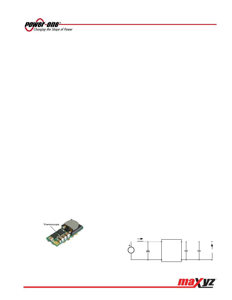
�The� output� voltage� ripple� and� input� reflected-ripple�
�current� waveforms� are� obtained� using� the� test� setup�
�shown� in� Fig.� G.�
�i� S�
�Fig.� F:� Location� of� the� thermocouple� for� thermal� testing.�
�1� ?� H�
�source�
�inductance�
�V� source�
�C� IN�
�4x47� ?� F�
�ceramic�
�capacitor�
�Y-Series�
�DC-DC�
�Converter�
�1� ?� F�
�ceramic�
�capacitor�
�C� O�
�100� ?� F�
�ceramic�
�capacitor�
�Vout�
�Thermal� Derating�
�Load� current� vs.� ambient� temperature� and� airflow�
�rates� are� given� in� Figs.� x.1� and� Figs.� x.2� for�
�maximum� temperature� of� 120°C.� Ambient�
�Fig.� G:� Test� setup� for� measuring� input� reflected-ripple� currents,� i� s�
�and� output� voltage� ripple.�
�MCD10205� Rev.� 1.0,� 24-Jun-10�
�Page� 8� of� 25�
�www.power-one.com�
�相关PDF资料 |
PDF描述 |
|---|---|
| 74VHCT08AMTC | IC GATE AND QUAD 2INPUT 14TSSOP |
| 74HCT4060N,652 | IC 14STAGE BINARY RIPPLE 16DIP |
| 74HCT193N,652 | IC COUNTER UP/DOWN SYNC 16-DIP |
| 74HCT160N,652 | IC SYNC BCD DECADE COUNT 16-DIP |
| 74HC4024D,653 | IC 7STAGE BINARY RIPPLE 14SOIC |
相关代理商/技术参数 |
参数描述 |
|---|---|
| YS-1 | 制造商:Taiyo Electric Ind. 功能描述: |
| YS10 | 制造商:Norma Products Midlands 功能描述:10MM ID HOSE Y CONNECTOR |
| YS-100 | 制造商:Taiyo Electric Ind. 功能描述: |
| YS10-01B-S | 制造商:Klixon 功能描述:THERMAL PROTECTOR |
| YS1005A | 制造商:Cosel Usa Inc 功能描述:Power Supply;AC-DC;5V@2A;85-132V In;Enclosed;Thru Hole;Switching;YS Series 制造商:Cosel Usa Inc 功能描述:AC/DC Power Supply Single-OUT 5V 2A 10W 5-Pin Bulk |
发布紧急采购,3分钟左右您将得到回复。