- 您现在的位置:买卖IC网 > PDF目录152475 > 1-100707-01 (SENSITRON SEMICONDUCTOR) DIGITAL TEMP SENSOR-SERIAL, 14BIT(s), SQUARE, SURFACE MOUNT PDF资料下载
参数资料
| 型号: | 1-100707-01 |
| 厂商: | SENSITRON SEMICONDUCTOR |
| 元件分类: | Switch/Digital Output Temperature Sensor |
| 英文描述: | DIGITAL TEMP SENSOR-SERIAL, 14BIT(s), SQUARE, SURFACE MOUNT |
| 封装: | ROHS COMPLIANT PACKAGE, 6 PIN |
| 文件页数: | 11/12页 |
| 文件大小: | 332K |
| 代理商: | 1-100707-01 |
Datasheet SHT21
www.sensirion.com
Version 1.1 – May 2010
8/12
5.4
Hold / No Hold Master Mode
There are two different operation modes to communicate
with the sensor: Hold Master mode or No Hold Master
mode. In the first case the SCL line is blocked (controlled
by sensor) during measurement process while in the latter
case the SCL line remains open for other communication
while the sensor is processing the measurement. No hold
master
mode
allows
for
processing
other
I2C
communication tasks on a bus while the sensor is
measuring. A communication sequence of the two modes
is displayed in Figure 15 and Figure 16, respectively.
In the hold master mode, the SHT2x pulls down the SCL
line while measuring to force the master into a wait state.
By releasing the SCL line the sensor indicates that internal
processing is terminated and that transmission may be
continued.
1
2
3
4
5
6
7
8
9
10
11
12
13
14
15
16
17
18
S 1 0 0 0 0 0 0 0
AC
K
1 1 1 0 0 1 0 1
AC
K
I2C address + write
Command (see Table 6)
19
20
21
22
23
24
25
26
27
S 1 0 0 0 0 0 0 1
AC
K
Measurement
I2C address + read
Hold during measurement
28
29
30
31
32
33
34
35
36
37
38
39
40
41
42
43
44
45
0 1 1 0 0 0 1 1
AC
K
0 1 0 1 0 0 1 0
AC
K
Data (MSB)
Data (LSB) Stat.
46
47
48
49
50
51
52
53
54
0 1 1 0 0 0 1 1
N
A
C
K
P
Checksum
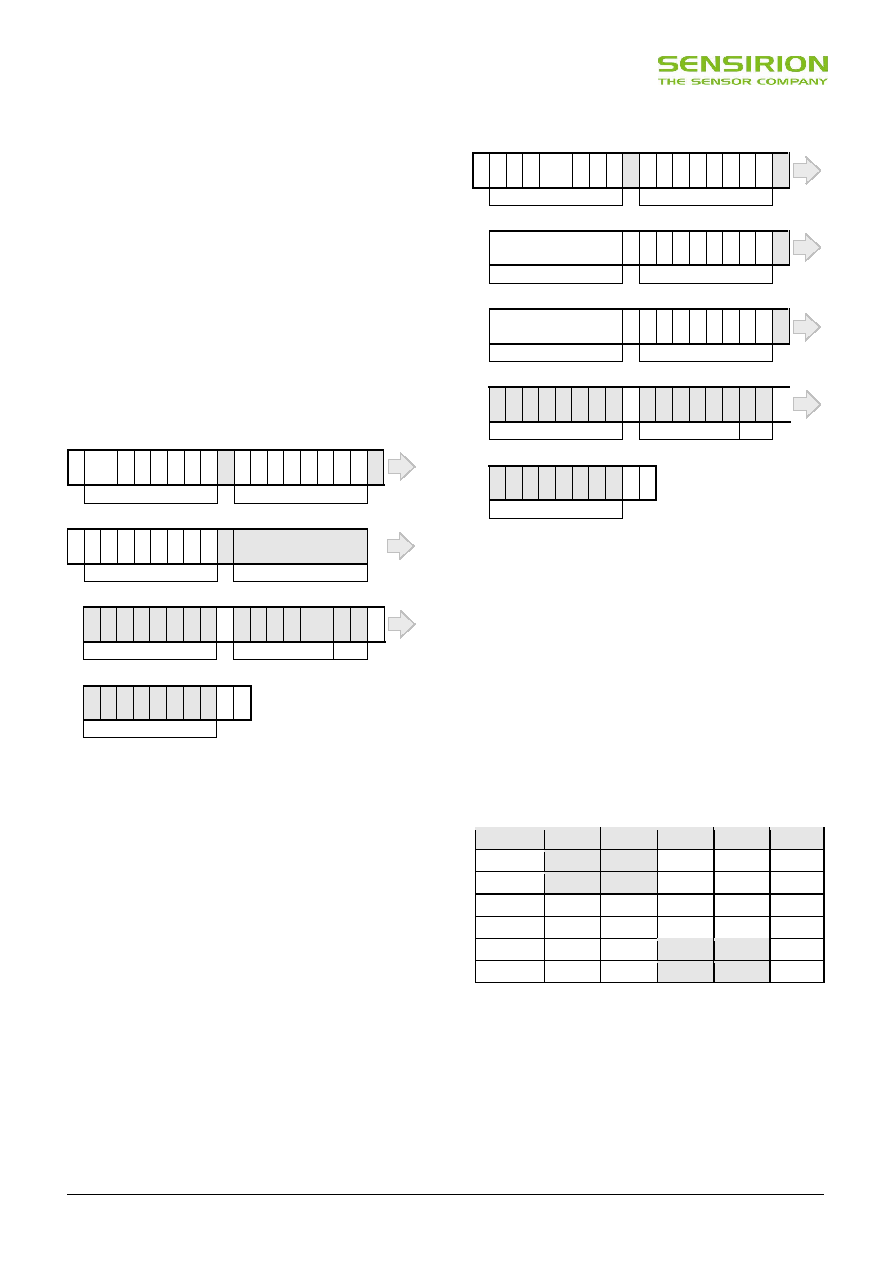
Figure 15 Hold master communication sequence – grey blocks
are controlled by SHT2x. Bit 45 may be changed to NACK
followed by Stop condition (P) to omit checksum transmission.
In no hold master mode, the MCU has to poll for the
termination of the internal processing of the sensor. This is
done by sending a Start condition followed by the I2C
header (1000’0001) as shown in Figure 16. If the internal
processing is finished, the sensor acknowledges the poll of
the MCU and data can be read by the MCU. If the
measurement processing is not finished the sensor
answers no ACK bit and the Start condition must be
issued once more.
For both modes, since the maximum resolution of a
measurement is 14 bit, the two last least significant bits
(LSBs, bits 43 and 44) are used for transmitting status
information. Bit 1 of the two LSBs indicates the
measurement type (‘0’: temperature, ‘1’ humidity). Bit 0 is
currently not assigned.
1
2
3
4
5
6
7
8
9
10
11
12
13
14
15
16
17
18
S 1 0 0 0 0 0 0 0
AC
K
1 1 1 1 0 1 0 1
AC
K
I2C address + write
Command (see Table 6)
19
20
21
22
23
24
25
26
27
Measurement
S 1 0 0 0 0 0 0 1
N
A
C
K
measuring
I2C address + read
19
20
21
22
23
24
25
26
27
Measurement
S 1 0 0 0 0 0 0 1
AC
K
continue measuring
I2C address + read
28
29
30
31
32
33
34
35
36
37
38
39
40
41
42
43
44
45
0 1 1 0 0 0 1 1
AC
K
0 1 0 1 0 0 1 0
AC
K
Data (MSB)
Data (LSB) Stat.
46
47
48
49
50
51
52
53
54
0 1 1 0 0 0 1 1
N
A
C
K
P
Checksum
Figure 16 No Hold master communication sequence – grey
blocks are controlled by SHT2x. If measurement is not
completed upon “read” command, sensor does not provide ACK
on bit 27 (more of these iterations are possible). If bit 45 is
changed to NACK followed by Stop condition (P) checksum
transmission is omitted.
In the examples given in Figure 15 and Figure 16 the
sensor output is SRH = ‘0110’0011’0101’0000’. For the
calculation of physical values Status Bits must be set to ‘0’
– see Chapter 6.
The maximum duration for measurements depends on the
type of measurement and resolution chosen – values are
displayed in Table 7. Maximum values shall be chosen for
the communication planning of the MCU.
Resolution
RH typ
RH max
T typ
T max
Units
14 bit
66
85
ms
13 bit
33
43
ms
12 Bit
22
29
17
22
ms
11 bit
12
15
9
11
ms
10 bit
7
9
ms
8 bit
3
4
ms
Table 7 Measurement times for RH and T measurements at
different resolutions. Typical values are recommended for
calculating energy consumption while maximum values shall be
applied for calculating waiting times in communication.
Please note: I2C communication allows for repeated Start
conditions (S) without closing prior sequence with Stop
condition (P) – compare Figures 15, 16 and 18. Still, any
sequence with adjacent Start condition may alternatively
be closed with a Stop condition.
相关PDF资料 |
PDF描述 |
|---|---|
| 1-100645-01 | DIGITAL TEMP SENSOR-SERIAL, 14BIT(s), SQUARE, SURFACE MOUNT |
| 1-102154-0 | 50 CONTACT(S), MALE, STRAIGHT TWO PART BOARD CONNECTOR, SOLDER |
| 1-102154-1 | 60 CONTACT(S), MALE, STRAIGHT TWO PART BOARD CONNECTOR, SOLDER |
| 1-102154-2 | 64 CONTACT(S), MALE, STRAIGHT TWO PART BOARD CONNECTOR, SOLDER |
| 1-102321-0 | 50 CONTACT(S), MALE, STRAIGHT TWO PART BOARD CONNECTOR, SOLDER |
相关代理商/技术参数 |
参数描述 |
|---|---|
| 11-007082-000 | 制造商:Amphenol Corporation 功能描述:11-007082-000 - Bulk |
| 11-007-172 | 功能描述:电缆组件 FLAT PIN STAKED FLEX MALE/FEMALE TIN ENDS RoHS:否 制造商:Molex 产品:Power Assemblies 类型:Cable Assembly 连接器端口 A:No Connector 连接器端口 A 管脚计数:4 连接器端口 B:No Connector 连接器端口 B 管脚计数: 型式:Male 线规 - 美国线规(AWG):20, 28 长度:0.305 m 颜色:Black, Red |
| 11-007295-000 | 制造商:Amphenol Corporation 功能描述:11-007295-000 - Bulk |
| 11-007345-000 | 制造商:Amphenol Corporation 功能描述:11-007345-000 - Bulk |
| 11-007368-000 | 制造商:Amphenol Corporation 功能描述:TOOL - Bulk |
发布紧急采购,3分钟左右您将得到回复。