参数资料
| 型号: | 101-0411 |
| 厂商: | Rabbit Semiconductor |
| 文件页数: | 26/90页 |
| 文件大小: | 0K |
| 描述: | INTERFACE 12KEYDISP ETHNT OP6700 |
| 标准包装: | 25 |
| 系列: | SBC |
| 模块/板类型: | 单板计算机模块 |
| 适用于相关产品: | OP6700 |
第1页第2页第3页第4页第5页第6页第7页第8页第9页第10页第11页第12页第13页第14页第15页第16页第17页第18页第19页第20页第21页第22页第23页第24页第25页当前第26页第27页第28页第29页第30页第31页第32页第33页第34页第35页第36页第37页第38页第39页第40页第41页第42页第43页第44页第45页第46页第47页第48页第49页第50页第51页第52页第53页第54页第55页第56页第57页第58页第59页第60页第61页第62页第63页第64页第65页第66页第67页第68页第69页第70页第71页第72页第73页第74页第75页第76页第77页第78页第79页第80页第81页第82页第83页第84页第85页第86页第87页第88页第89页第90页
28
Intellicom (OP6600/OP6700)
3.4 Memory
3.4.1 SRAM
The Intellicom is designed to accept 32K to 512K of SRAM packaged in an SOIC case.
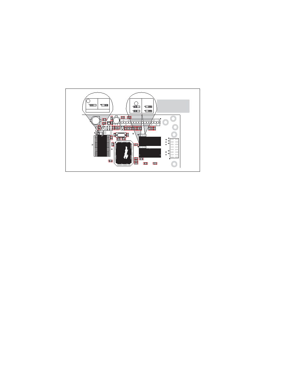
The standard models come with 128K of SRAM. Figure 12 shows the locations and the
jumper settings for the jumpers at JP1 used to set the SRAM size. The “jumpers” are 0
surface-mounted resistors.
Figure 12. Intellicom Jumper Settings
for SRAM and Flash EPROM Size
3.4.2 Flash Memory
The Intellicom is also designed to accept 128K to 512K of flash memory packaged in a
TSOP case.
The Intellicom OP6700 comes with two 256K flash memory chips, and the Intellicom
OP6600 comes with one 256K flash memory. Figure 12 shows the locations and the
jumper settings for the jumpers at JP2 and JP3 used to set the flash memory size. The
“jumpers” are 0
surface-mounted resistors.
NOTE: Rabbit recommends that any customer applications should not be constrained by
the sector size of the flash EPROM since it may be necessary to change the sector size
in the future.
A Flash Memory Bank Select jumper configuration option exists at JP5 with 0
surface-
mounted resistors. This option, used in conjunction with some configuration macros, allows
Dynamic C to compile two different co-resident programs for the upper and lower halves of
the 256K flash in such a way that both programs start at logical address 0000. This is useful
for applications that require a resident download manager and a separate downloaded pro-
gram. See Technical Note 218, Implementing a Serial Download Manager for a 256K
Flash, for details.
3.4.3 Dynamic C BIOS Source Files
The Dynamic C BIOS source files handle different standard RAM and flash EPROM sizes
automatically.
3
2
1
3
2
1
128K
JP1
512K
SRAM
3
2
1
JP2
3
2
1
128K/256K
JP2
512K
Flash EPROM
R38
90
15
65
40
U4
C18
U3
TP1
R9
R8
R10
C4
R4
R2
R7
R1
+
C2
Q1
R3
JP1
C6
U1
R11
R12
R13
R5
2
1
J2
Q2
R15
R14
R6
C5
+
C3
C9
R28
C10
C1
1
C12
TP2
Y1
R27
JP2
JP3
U5
C13
TP10
R18
R17
C7
R16
R19
R20
R21
R22
TP18
TP17
TP19
TP16
TP15
TP14
TP13
TP12
TP11
R86
R85
U6
C19
C20
C17
TP20
15
J3
C21
4 X 20 LCD
GND
2 X 20 LCD
SRAM
Flash
EPROM
Flash
EPROM
JP1
FD
No jumper = 32K
FD
JP3
Note that the OP6600 has
only one flash EPROM
installed at U5, and so there
are no jumpers at JP3.
相关PDF资料 |
PDF描述 |
|---|---|
| AT24C02A-10PI-2.7 | IC EEPROM 2KBIT 400KHZ 8DIP |
| AT24C02A-10PI-1.8 | IC EEPROM 2KBIT 400KHZ 8DIP |
| 25FMN-BMT-A-TF | CONN FMN HSNG 25POS SNGL NOR SMD |
| 046239012001800+ | CONN FPC ONE-TOUCH LCK .5MM 12 |
| AT24C01-10PI-1.8 | IC EEPROM 1KBIT 400KHZ 8DIP |
相关代理商/技术参数 |
参数描述 |
|---|---|
| 10104110 | 制造商:FCI-CONNECTOR 制造商全称:FCI connector 功能描述:MICRO USB B TYPE RECEPTACLE |
| 10104110-0001LF | 功能描述:USB接头 5P Quick Connect Micro USB TypeB Rcpt RoHS:否 制造商:FCI 产品:USB Type A Connectors 标准:USB 3.0 端口数量: 位置/触点数量:9 型式:Female 电流额定值:1.8 A 安装风格:Through Hole 端接类型:Solder Pin 连接器类型:USB 3.0 Receptacle |
| 10104110-0001LF | 制造商:FCI 功能描述:MICRO USB B, RECEPTACLE, 5POS, SMT RT AN |
| 10-104-11-01 | 制造商:Concord Electronics Inc 功能描述:Contact Solder ST Thru-Hole |
| 10-104-11-03 | 制造商:Concord Electronics Inc 功能描述: |
发布紧急采购,3分钟左右您将得到回复。