- 您现在的位置:买卖IC网 > PDF目录293745 > 1893YI-10 (INTEGRATED DEVICE TECHNOLOGY INC) DATACOM, INTERFACE CIRCUIT, PQFP64 PDF资料下载
参数资料
| 型号: | 1893YI-10 |
| 厂商: | INTEGRATED DEVICE TECHNOLOGY INC |
| 元件分类: | 网络接口 |
| 英文描述: | DATACOM, INTERFACE CIRCUIT, PQFP64 |
| 封装: | 10 X 10 MM, TQFP-64 |
| 文件页数: | 14/152页 |
| 文件大小: | 943K |
| 代理商: | 1893YI-10 |
第1页第2页第3页第4页第5页第6页第7页第8页第9页第10页第11页第12页第13页当前第14页第15页第16页第17页第18页第19页第20页第21页第22页第23页第24页第25页第26页第27页第28页第29页第30页第31页第32页第33页第34页第35页第36页第37页第38页第39页第40页第41页第42页第43页第44页第45页第46页第47页第48页第49页第50页第51页第52页第53页第54页第55页第56页第57页第58页第59页第60页第61页第62页第63页第64页第65页第66页第67页第68页第69页第70页第71页第72页第73页第74页第75页第76页第77页第78页第79页第80页第81页第82页第83页第84页第85页第86页第87页第88页第89页第90页第91页第92页第93页第94页第95页第96页第97页第98页第99页第100页第101页第102页第103页第104页第105页第106页第107页第108页第109页第110页第111页第112页第113页第114页第115页第116页第117页第118页第119页第120页第121页第122页第123页第124页第125页第126页第127页第128页第129页第130页第131页第132页第133页第134页第135页第136页第137页第138页第139页第140页第141页第142页第143页第144页第145页第146页第147页第148页第149页第150页第151页第152页
ICS1893 Rev C 6/6/00
June, 2000
110
Chapter 9
Pin Diagram, Listings, and Descriptions
ICS1893 Data Sheet - Release
Copyright 2000, Integrated Circuit Systems, Inc.
All rights reserved.
9.3.3
Configuration Pins
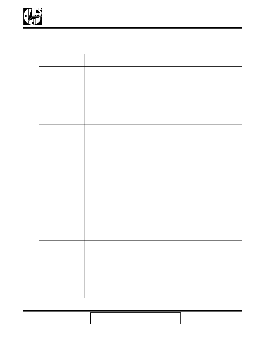
Table 9-4 lists the configuration pins.
Table 9-4.
Configuration Pins
Pin
Name
Pin
Number
Pin
Type
Pin Description
10/100SEL
2
Input or
Output
10Base-T / 100Base-TX Select.
The ‘Pin Type’for this pin depends on the setting for the HW/SW pin
(pin 23). When the HW/SW pin is set for:
Hardware mode, this pin acts as an input. In this case, when the
signal on this pin is logic:
– Low, this pin selects 10Base-T operations.
– High, this pin selects 100Base-TX operations.
Software mode, this pin acts as an output that indicates the current
status of this pin. In this case, when the signal on this pin is logic:
– Low, this pin indicates 10Base-T operations are selected.
– High, this pin indicates 100Base-TX operations are selected.
10TCSR
9
Input
10M Transmit Current Set Resistor.
A resistor, connected between this pin and ground, is required to
establish the value of the transmit current used in 10Base-T mode.
The value and tolerance of this resistor is specified in Section 10.3,
“Recommended Component Values”.
100TCSR
10
Input
100M Transmit Current Set Resistor.
A resistor, connected between this pin and ground, is required to
establish the value of the transmit current used in 100Base-TX
mode.
The value and tolerance of this resistor is specified in Section 10.3,
“Recommended Component Values”.
ANSEL
26
Input or
Output
Auto-Negotiation Select.
The ‘Pin Type’for this pin depends on the setting for the HW/SW pin
(pin 23). When the HW/SW pin is set for:
Hardware mode, this pin acts as an input. In this case, when the
signal on this pin is logic:
– Low, this pin does not select Auto-Negotiation operations.
– High, this pin selects Auto-Negotiation operations.
Software mode, this pin acts as an output that indicates the current
status of this pin. In this case, when the signal on this pin is logic:
– Low, this pin indicates that Auto-Negotiation is disabled.
– High, this pin indicates that Auto-Negotiation is enabled.
DPXSEL
24
Input or
Output
Half-Duplex / Full-Duplex Select.
The ‘Pin Type’for this pin depends on the setting for the HW/SW pin
(pin 23). When the HW/SW pin is set for:
Hardware mode, this pin acts as an input. In this case, when the
signal on this pin is logic:
– Low, this pin selects half-duplex operations.
– High, this pin selects full-duplex operations.
Software mode, this pin acts as an output that indicates the current
status of this pin. In this case, when the signal on this pin is logic:
– Low, this pin indicates that it is set for half-duplex operations.
– High, this pin indicates that it is set for full-duplex operations.
相关PDF资料 |
PDF描述 |
|---|---|
| 1894-40KLF | DATACOM, INTERFACE CIRCUIT, QCC40 |
| 1894-40KLFT | DATACOM, INTERFACE CIRCUIT, QCC40 |
| 1895230000 | 15 A, STRIP TERMINAL BLOCK, 2 ROWS, 2 DECKS |
| 18F-08P-241 | 8 CONTACT(S), CABLE MOUNT, MINI DIN CONNECTOR, PLUG |
| 18F-08P-244 | 8 CONTACT(S), CABLE MOUNT, MINI DIN CONNECTOR, PLUG |
相关代理商/技术参数 |
参数描述 |
|---|---|
| 1893YI-10LF | 功能描述:以太网 IC 3.3V 10/100 BASE TX INTEGRATED PHYCEIVER RoHS:否 制造商:Micrel 产品:Ethernet Switches 收发器数量:2 数据速率:10 Mb/s, 100 Mb/s 电源电压-最大:1.25 V, 3.45 V 电源电压-最小:1.15 V, 3.15 V 最大工作温度:+ 85 C 封装 / 箱体:QFN-64 封装:Tray |
| 1893YI-10LFT | 功能描述:以太网 IC 3.3V 10/100 BASE TX INTEGRATED PHYCEIVER RoHS:否 制造商:Micrel 产品:Ethernet Switches 收发器数量:2 数据速率:10 Mb/s, 100 Mb/s 电源电压-最大:1.25 V, 3.45 V 电源电压-最小:1.15 V, 3.15 V 最大工作温度:+ 85 C 封装 / 箱体:QFN-64 封装:Tray |
| 1894 | 功能描述:支架与垫片 HEX .187X.625 ALUM RoHS:否 制造商:Schurter 类型:Transipillar Spacers 长度:16 m 螺纹大小:M4 外径:10 mm 材料:Nylon with Steel 电镀:Zinc |
| 1894# | 制造商:Fluke Electronics 功能描述:BNC (F)/BANANA PLUG 制造商:Pomona Electronics 功能描述: |
| 1894 | 制造商:Pomona Electronics 功能描述:ADAPTER BNC FEMALE-BANANA PLUG 制造商:Pomona Electronics 功能描述:ADAPTER, BNC FEMALE-BANANA PLUG |
发布紧急采购,3分钟左右您将得到回复。