- 您现在的位置:买卖IC网 > PDF目录33797 > 45IZ (Intersil Corporation) 5V or 12V Single Synchronous Buck Pulse-Width Modulation (PWM) Controller PDF资料下载
参数资料
| 型号: | 45IZ |
| 厂商: | Intersil Corporation |
| 英文描述: | 5V or 12V Single Synchronous Buck Pulse-Width Modulation (PWM) Controller |
| 中文描述: | 单5V或12V同步降压脉宽调制(PWM)控制器 |
| 文件页数: | 2/16页 |
| 文件大小: | 302K |
| 代理商: | 45IZ |
www.DataSheet4U.com
10
FN6305.3
November 15, 2006
(to be sure the sample time is long enough), which can also
help refresh the boot. But if OCP is disabled (no current
sense resistor), the regular boot refresh circuit will still be
active.
Current Sinking
The ISL6545 incorporates a MOSFET shoot-through
protection method which allows a converter to sink current
as well as source current. Care should be exercised when
designing a converter with the ISL6545 when it is known that
the converter may sink current.
When the converter is sinking current, it is behaving as a
boost converter that is regulating its input voltage. This
means that the converter is boosting current into the VCC
rail, which supplies the bias voltage to the ISL6545. If there
is nowhere for this current to go, such as to other distributed
loads on the VCC rail, through a voltage limiting protection
device, or other methods, the capacitance on the VCC bus
will absorb the current. This situation will allow voltage level
of the VCC rail to increase. If the voltage level of the rail is
boosted to a level that exceeds the maximum voltage rating
of the ISL6545, then the IC will experience an irreversible
failure and the converter will no longer be operational.
Ensuring that there is a path for the current to follow other
than the capacitance on the rail will prevent this failure
mode.
Application Guidelines
Layout Considerations
As in any high frequency switching converter, layout is very
important. Switching current from one power device to another
can generate voltage transients across the impedances of the
interconnecting bond wires and circuit traces. These
interconnecting impedances should be minimized by using
wide, short printed circuit traces. The critical components
should be located as close together as possible, using ground
plane construction or single point grounding.
Figure 7 shows the critical power components of the converter.
To minimize the voltage overshoot, the interconnecting wires
indicated by heavy lines should be part of a ground or power
plane in a printed circuit board. The components shown should
be located as close together as possible. Please note that the
capacitors CIN and CO may each represent numerous physical
capacitors. For best results, locate the ISL6545 within 1 inch of
the MOSFETs, Q1 and Q2. The circuit traces for the MOSFET
gate and source connections from the ISL6545 must be sized
to handle up to 1A peak current.
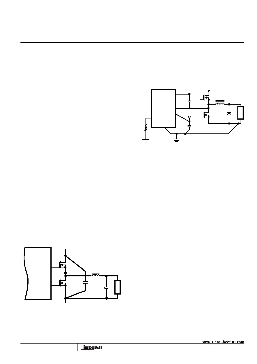
Figure 8 shows the circuit traces that require additional
layout consideration. Use single point and ground plane
construction for the circuits shown. Minimize any leakage
current paths on the COMP/SD pin and locate the resistor,
ROSCET close to the COMP/SD pin because the internal
current source is only 20
μA. Provide local V
CC decoupling
between VCC and GND pins. Locate the capacitor, CBOOT
as close as practical to the BOOT and PHASE pins. All
components used for feedback compensation (not shown)
should be located as close to the IC as practical.
Feedback Compensation
This section highlights the design consideration for a voltage-
mode controller requiring external compensation. To address a
broad range of applications, a type-3 feedback network is
recommended, as shown in the top part of Figure 9.
Figure 9 also highlights the voltage-mode control loop for a
synchronous-rectified buck converter, applicable to the
ISL6545 circuit. The output voltage (VOUT) is regulated to the
reference voltage, VREF. The error amplifier output (COMP pin
voltage) is compared with the oscillator (OSC) modified saw-
tooth wave to provide a pulse-width modulated wave with an
amplitude of VIN at the PHASE node. The PWM wave is
smoothed by the output filter (L and C). The output filter
capacitor bank’s equivalent series resistance is represented by
the series resistor E.
LO
CO
LGATE/OCSET
UGATE
PHASE
Q1
Q2
VIN
VOUT
RETURN
ISL6545
CIN
LO
AD
FIGURE 7. PRINTED CIRCUIT BOARD POWER AND
GROUND PLANES OR ISLANDS
FIGURE 8. PRINTED CIRCUIT BOARD SMALL SIGNAL
LAYOUT GUIDELINES
+VCC
ISL6545
LGATE/OCSET
GND
VCC
BOOT
LO
CO
VOUT
LO
AD
Q1
Q2
PHASE
+VIN
CBOOT
CVCC
R
OC
SET
ISL6545, ISL6545A
相关PDF资料 |
PDF描述 |
|---|---|
| 45L(R)SERIES | Dual/Triple Ultra-Low-Voltage SOT23 µP Supervisory Circuits |
| 45L(R) | STANDARD RECOVERY DIODES Stud Version |
| 45L100 | Standard Recovery Diodes(标准修复二极管) |
| 45L10 | STANDARD RECOVERY DIODES Stud Version |
| 45L120D | Standard Recovery Diodes(标准修复二极管) |
相关代理商/技术参数 |
参数描述 |
|---|---|
| 45J100 | 功能描述:线绕电阻器 - 透孔 5watt 100ohm 5% Axial RoHS:否 制造商:Bourns 电阻:10 Ohms 容差:5 % 功率额定值:7 W 温度系数:200 PPM / C 系列:FW 端接类型:Axial 工作温度范围:- 55 C to + 155 C 尺寸:9.5 mm Dia. x 26 mm L 封装:Ammo 产品:Power Resistors Wirewound High Energy |
| 45J100E | 功能描述:线绕电阻器 - 透孔 5watt 100ohm 5% Axial RoHS:否 制造商:Bourns 电阻:10 Ohms 容差:5 % 功率额定值:7 W 温度系数:200 PPM / C 系列:FW 端接类型:Axial 工作温度范围:- 55 C to + 155 C 尺寸:9.5 mm Dia. x 26 mm L 封装:Ammo 产品:Power Resistors Wirewound High Energy |
| 45J10K | 功能描述:线绕电阻器 - 透孔 5watt 10K 5% Axial RoHS:否 制造商:Bourns 电阻:10 Ohms 容差:5 % 功率额定值:7 W 温度系数:200 PPM / C 系列:FW 端接类型:Axial 工作温度范围:- 55 C to + 155 C 尺寸:9.5 mm Dia. x 26 mm L 封装:Ammo 产品:Power Resistors Wirewound High Energy |
| 45J10KE | 功能描述:线绕电阻器 - 透孔 5watt 10K 5% Axial RoHS:否 制造商:Bourns 电阻:10 Ohms 容差:5 % 功率额定值:7 W 温度系数:200 PPM / C 系列:FW 端接类型:Axial 工作温度范围:- 55 C to + 155 C 尺寸:9.5 mm Dia. x 26 mm L 封装:Ammo 产品:Power Resistors Wirewound High Energy |
| 45J10R | 功能描述:线绕电阻器 - 透孔 5watt 10ohm 5% Axial RoHS:否 制造商:Bourns 电阻:10 Ohms 容差:5 % 功率额定值:7 W 温度系数:200 PPM / C 系列:FW 端接类型:Axial 工作温度范围:- 55 C to + 155 C 尺寸:9.5 mm Dia. x 26 mm L 封装:Ammo 产品:Power Resistors Wirewound High Energy |
发布紧急采购,3分钟左右您将得到回复。