- 您现在的位置:买卖IC网 > PDF目录156623 > 4610M-901-103 KONDENSATOR NETZWERK PDF资料下载
参数资料
| 型号: | 4610M-901-103 |
| 英文描述: | KONDENSATOR NETZWERK |
| 中文描述: | KONDENSATOR NETZWERK |
| 文件页数: | 43/62页 |
| 文件大小: | 1883K |
| 代理商: | 4610M-901-103 |
第1页第2页第3页第4页第5页第6页第7页第8页第9页第10页第11页第12页第13页第14页第15页第16页第17页第18页第19页第20页第21页第22页第23页第24页第25页第26页第27页第28页第29页第30页第31页第32页第33页第34页第35页第36页第37页第38页第39页第40页第41页第42页当前第43页第44页第45页第46页第47页第48页第49页第50页第51页第52页第53页第54页第55页第56页第57页第58页第59页第60页第61页第62页
Specifications are subject to change without notice.
324
FOR PRODUCT SPECIFICATIONS, SEE PAGES 309 - 311.
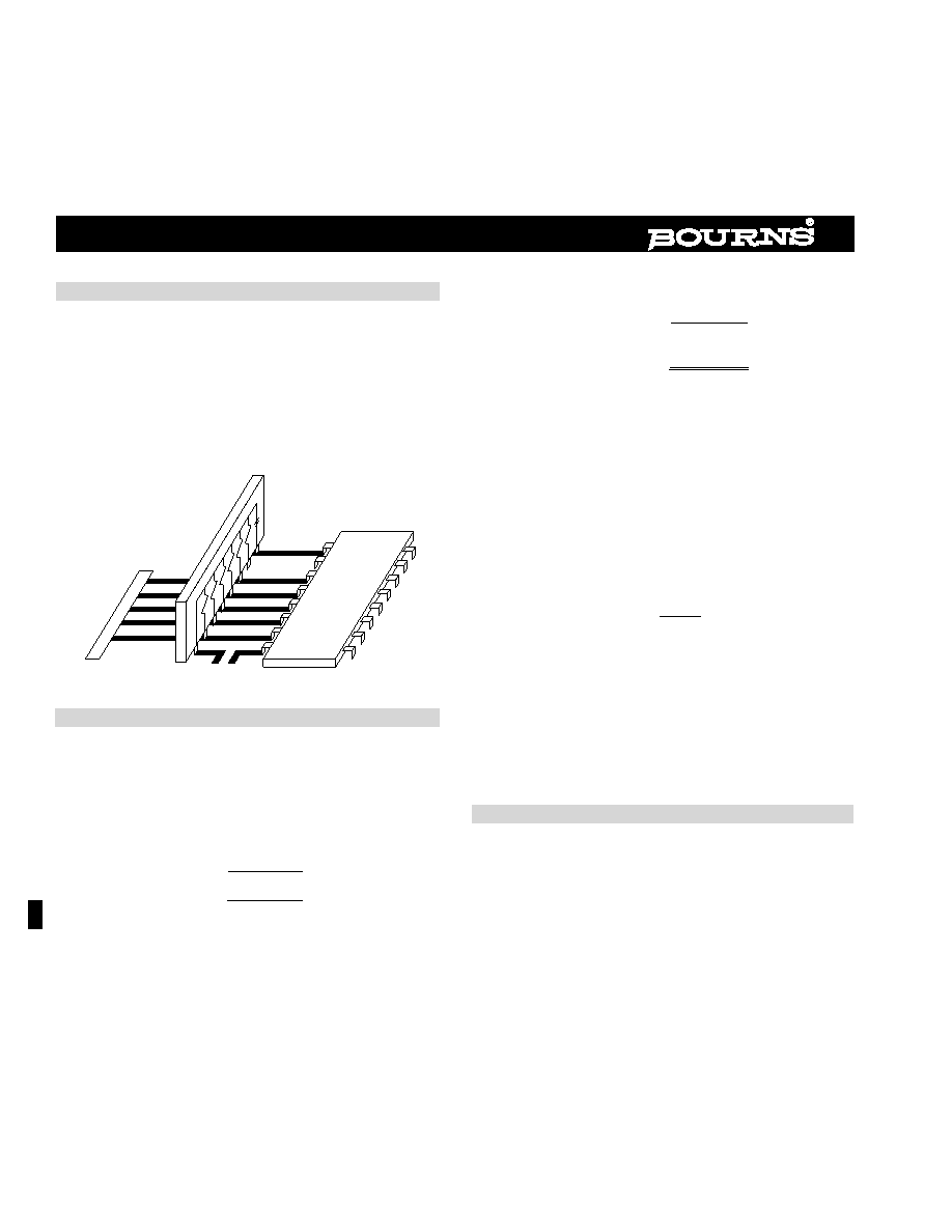
Typical Application
A typical application using a Bourns 801 RC Network in con-
junction with a 10K ECL design is shown below. Vee is typically
connected to -5.2 volts (10K ECL) or -4.5 volts (100K ECL). Vcc
is typically connected to GND. Vtt is typically connected to -2.0
volts. The 801 network shown below can terminate up to 6
transmission lines and provides a 0.01
F capacitor to reduce
cross talk and feedthrough effects.
The actual, effective delay and impedance due to
loading from stubs or additional devices off the line will be:
Tpd’ = Tpd √1 + Cd/Co
Zo
Zo’ =
√1 + (C
d/Co)
Where Co = intrinsic capacitance of the line
Cd = capacitance due to loading and stubs
off the line
Tpd = basic propagation delay of the line
Zo ....= basic impedance of the line
To formulate a guideline for when line termination is
necessary, take the ratio of the rise time or fall time and the two-
way delay along the line. The maximum length for unterminated
lines will result as follows:
Lmax =
Tr
2Tpd’
Where Tr = rise or fall time
Tpd = propagation delay per unit length
The above equation implies that the faster the edge rate or the
higher the loading on the line (i.e., higher fanout), the more likely
that termination will be necessary for a given line length.
Parallel Termination
For maximum circuit performance or distributed loads, parallel
termination is the most appropriate technique. A parallel termi-
nated line uses a resistor connected to -2 volts (ECL application)
at the receiving end. The resistor value matches the characteris-
tic impedance of the line (Zo), thereby producing zero reflection
at the receiver. In addition, the terminating resistor also provides
output pull down, so a separate pull down resistor at the driving
end is unnecessary.
Transmission Line Considerations
In high speed circuit applications, the signal propagation delay
(Tpd) and characteristic impedance (zo), along a printed circuit
board line must be taken into consideration. In general, if the
two-way delay along the line is greater than the rise or fall time
of the signal, then controlled impedance techniques (i.e., termi-
nation) must be utilized to prevent undesirable ringing or over-
and undershoots. The delay and impedance can be calculated
by knowing the intrinsic inductance (Lo) and capacitance (Co) of
the line:
Tpd = √LoCo
Zo =
√L
o/Co
Vcc1
Aout
A1in
Vee
Vcc2
Bout
B1in
A1in
A2in
B1in
B2in
A2in,
MC10H118 MECL 10KH
Vee
TRANSMISSION
LINES
Vtt
BOURNS 801
10K ECL TERMINATOR
Bourns Emitter Coupled Logic Terminator 800 Series
相关PDF资料 |
PDF描述 |
|---|---|
| 4610M-901-104 | Dual/Triple Ultra-Low-Voltage SOT23 µP Supervisory Circuits |
| 4610M-902-103 | KONDENSATOR NETZWERK |
| 4610M-902-104 | Dual/Triple Ultra-Low-Voltage SOT23 µP Supervisory Circuits |
| 4610X-101-101 | WIDERSTAND NETZWERK DICKFILM 100R 5ST |
| 4610X-101-102 | Dual/Triple Ultra-Low-Voltage SOT23 µP Supervisory Circuits |
相关代理商/技术参数 |
参数描述 |
|---|---|
| 4610M-901-103LF | 功能描述:电容器阵列与网络 10Pin 0.01uF 20% Bussed X7R RoHS:否 制造商:AVX 电容:0.1 uF 容差:20 % 电压额定值:6.3 V 元件数量:2 工作温度范围: 外壳长度:0.8 mm 外壳宽度:1.6 mm 外壳高度:0.5 mm 端接类型:SMD/SMT 系列:PG |
| 4610M-901-104 | 功能描述:电容器阵列与网络 10Pin 0.1uF 20% Bussed X7R RoHS:否 制造商:AVX 电容:0.1 uF 容差:20 % 电压额定值:6.3 V 元件数量:2 工作温度范围: 外壳长度:0.8 mm 外壳宽度:1.6 mm 外壳高度:0.5 mm 端接类型:SMD/SMT 系列:PG |
| 4610M-901-104LF | 功能描述:电容器阵列与网络 10Pin 0.1uF 20% Bussed X7R RoHS:否 制造商:AVX 电容:0.1 uF 容差:20 % 电压额定值:6.3 V 元件数量:2 工作温度范围: 外壳长度:0.8 mm 外壳宽度:1.6 mm 外壳高度:0.5 mm 端接类型:SMD/SMT 系列:PG |
| 4610M-901-104LF | 制造商:Bourns Inc 功能描述:CAPACITOR ARRAY 0.1UF 50V X7R SIP 制造商:Bourns Inc 功能描述:CAPACITOR, ARRAY, 0.1UF, 50V, X7R, SIP |
| 4610M-901-104LF | 制造商:Bourns Inc 功能描述:CAPACITOR NETWORK 0.1UF ((NW)) |
发布紧急采购,3分钟左右您将得到回复。