- 您现在的位置:买卖IC网 > PDF目录117394 > 5962-8768102VEA (TEXAS INSTRUMENTS INC) 2.2 A SWITCHING CONTROLLER, 1180 kHz SWITCHING FREQ-MAX, CDIP16 PDF资料下载
参数资料
| 型号: | 5962-8768102VEA |
| 厂商: | TEXAS INSTRUMENTS INC |
| 元件分类: | 稳压器 |
| 英文描述: | 2.2 A SWITCHING CONTROLLER, 1180 kHz SWITCHING FREQ-MAX, CDIP16 |
| 封装: | CERAMIC, DIP-16 |
| 文件页数: | 9/15页 |
| 文件大小: | 503K |
| 代理商: | 5962-8768102VEA |
ABSOLUTE MAXIMUM RATINGS
www.ti.com ..................................................................................................................................................... SLUS873A – JANUARY 2009 – REVISED APRIL 2009
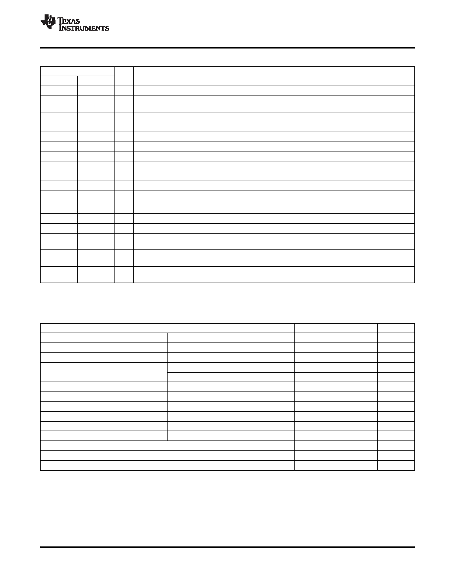
Terminal Functions
TERMINAL
I/O
DESCRIPTION
NAME
NO.
CLK/LEB
4
O
Output of the internal oscillator
Timing capacitor connection pin for oscillator frequency programming. The timing capacitor should be
CT
6
I
connected to the device ground using minimal trace length.
EAOUT
3
O
Output of the error amplifier for compensation
GND
10
Analog ground return pin
ILIM
9
I
Input to the current limit comparator
INV
1
I
Inverting input to the error amplifier
NI
2
I
Non-inverting input to the error amplifier
OUTA
11
O
High current totem pole output A of the on-chip drive stage.
OUTB
14
O
High current totem pole output B of the on-chip drive stage.
PGND
12
Ground return pin for the output driver stage
Non-inverting input to the PWM comparator with 1.25-V internal input offset. In voltage mode operation,
RAMP
7
I
this serves as the input voltage feed-forward function by using the CT ramp. In peak current mode
operation, this serves as the slope compensation input.
RT
5
I
Timing resistor connection pin for oscillator frequency programming
SS
8
I
Soft-start input pin which also doubles as the maximum duty cycle clamp.
Power supply pin for the output stage. This pin should be bypassed with a 0.1-
F monolithic ceramic
VC
13
low ESL capacitor with minimal trace lengths.
Power supply pin for the device. This pin should be bypassed with a 0.1-
F monolithic ceramic low ESL
VCC
15
capacitor with minimal trace lengths
5.1-V reference. For stability, the reference should be bypassed with a 0.1-
F monolithic ceramic low
VREF
16
O
ESL capacitor and minimal trace length to the ground plane.
over operating free-air temperature range unless otherwise noted
(1)
VALUE
UNIT
VIN
Supply voltage,
VC, VCC
22
V
IO
Source or sink current,DC
OUTA, OUTB
0.5
A
IO
Source or sink current, pulse (0.5
s)
OUTA, OUTB
2.2
A
INV, NI, RAMP
–0.3 to 7
V
Analog inputs
ILIM, SS
–0.3 to 6
V
Power ground
PGND
±0.2
V
Outputs
OUTA, OUTB
PGND - 0.3 to VC + 0.3
V
ICLK
Clock output current
CLK/LEB
–5
mA
IO(EA) Error amplifier output current
EAOUT
5
mA
ISS
Soft-start sink current
SS
20
mA
IOSC
Oscillator charging current
RT
–5
mA
TJ
Operating virtual junction temperature range
–55 to 150
°C
TSTG Storage temperature
–65 to 150
°C
Lead temperature 1,6 mm (1/16 inch) from cases for 10 seconds
300
°C
(1)
Stresses beyond those listed under absolute maximum ratings may cause permanent damage to the device. These are stress ratings
only, and functional operation of the device at these or any other conditions beyond those indicated under recommended operating
conditions is not implied. Exposure to absolute-maximum-rated conditions for extended periods may affect device reliability.
Copyright 2009, Texas Instruments Incorporated
3
Product Folder Link(s): UC1825A-SP
相关PDF资料 |
PDF描述 |
|---|---|
| 5962-0724303HXC | 1-OUTPUT 110 W DC-DC REG PWR SUPPLY MODULE |
| 555-0805-R27-G-00 | 1 ELEMENT, 0.27 uH, CERAMIC-CORE, GENERAL PURPOSE INDUCTOR, SMD |
| 555-1008-1R5-J-36 | 1 ELEMENT, 1.5 uH, CERAMIC-CORE, GENERAL PURPOSE INDUCTOR, SMD |
| 50A-821M-01 | 1 ELEMENT, 820 uH, FERRITE-CORE, GENERAL PURPOSE INDUCTOR |
| 501-0430 | 1 ELEMENT, 150 uH, FERRITE-CORE, GENERAL PURPOSE INDUCTOR |
相关代理商/技术参数 |
参数描述 |
|---|---|
| 5962-8768102XA | 制造商:Rochester Electronics LLC 功能描述:- Bulk |
| 5962-8768104V2A | 功能描述:电流型 PWM 控制器 High Spd PWM Controller RoHS:否 制造商:Texas Instruments 开关频率:27 KHz 上升时间: 下降时间: 工作电源电压:6 V to 15 V 工作电源电流:1.5 mA 输出端数量:1 最大工作温度:+ 105 C 安装风格:SMD/SMT 封装 / 箱体:TSSOP-14 |
| 5962-8768104VEA | 功能描述:电流型 PWM 控制器 High Spd PWM Controller RoHS:否 制造商:Texas Instruments 开关频率:27 KHz 上升时间: 下降时间: 工作电源电压:6 V to 15 V 工作电源电流:1.5 mA 输出端数量:1 最大工作温度:+ 105 C 安装风格:SMD/SMT 封装 / 箱体:TSSOP-14 |
| 5962-8768105VEA | 制造商:Texas Instruments 功能描述:Current Mode PWM Controller 100mA 16-Pin CDIP 制造商:Texas Instruments 功能描述:UC1825AJ-SP, HIGH SPEED PWM - Rail/Tube |
| 5962-87683012A | 制造商:Texas Instruments 功能描述:Decoder/Demultiplexer Dual 2-to-4 20-Pin LCCC Tube 制造商:Rochester Electronics LLC 功能描述:- Bulk |
发布紧急采购,3分钟左右您将得到回复。