- 您现在的位置:买卖IC网 > PDF目录97787 > 5962F9683401VCA (INTERSIL CORP) QUAD BUFFER AMPLIFIER, CDIP14 PDF资料下载
参数资料
| 型号: | 5962F9683401VCA |
| 厂商: | INTERSIL CORP |
| 元件分类: | 缓冲放大器 |
| 英文描述: | QUAD BUFFER AMPLIFIER, CDIP14 |
| 封装: | SIDE BRAZED, CERAMIC, DIP-14 |
| 文件页数: | 5/11页 |
| 文件大小: | 174K |
| 代理商: | 5962F9683401VCA |
3
PC Board Layout
This amplier’s frequency response depends greatly on the
care taken in designing the PC board (PCB). The use of low
inductance components such as chip resistors and chip
capacitors is strongly recommended, while a solid
ground plane is a must!
Attention should be given to decoupling the power supplies.
A large value (10
F) tantalum in parallel with a small value
(0.1
F) chip capacitor works well in most cases.
Terminated microstrip signal lines are recommended at the
input and output of the device. Capacitance directly on the
output must be minimized, or isolated as discussed in the
next section.
An example of a good high frequency layout is the
Evaluation Board shown in Figure 3.
Driving Capacitive Loads
Capacitive loads, such as an A/D input, or an improperly
terminated transmission line will degrade the amplier’s
phase margin resulting in frequency response peaking and
possible oscillations. In most cases, the oscillation can be
avoided by placing a resistor (RS) in series with the output
prior to the capacitance.
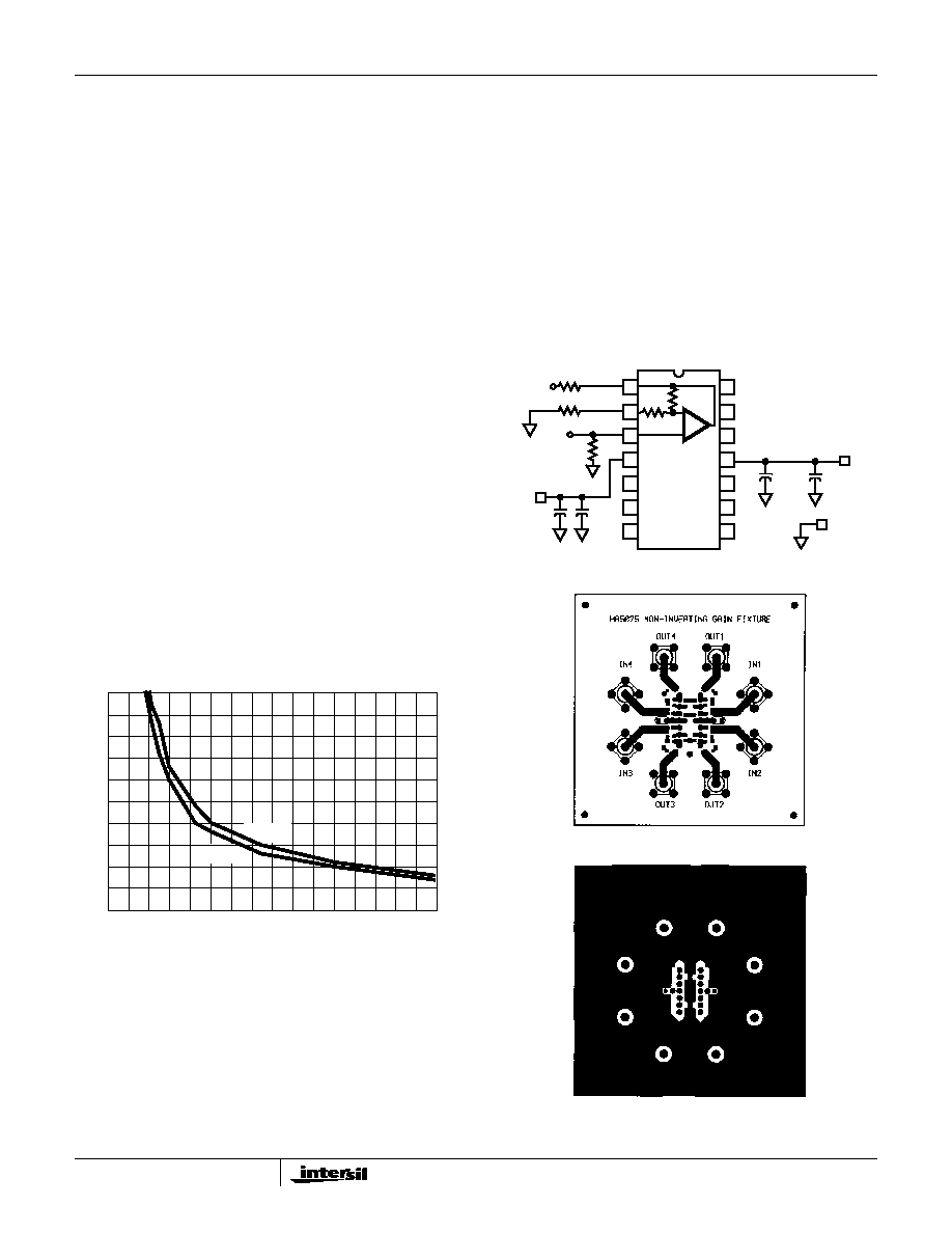
Figure 1 details starting points for the selection of this
resistor. The points on the curve indicate the RS and CL
combinations for the optimum bandwidth, stability, and
settling time, but experimental ne tuning is recommended.
Picking a point above or to the right of the curve yields an
overdamped response, while points below or left of the curve
indicate areas of underdamped performance.
RS and CL form a low pass network at the output, thus limiting
system bandwidth well below the amplifier bandwidth of
350MHz. By decreasing RS as CL increases (as illustrated in
the curves), the maximum bandwidth is obtained without
sacrificing stability. In spite of this, bandwidth decreases as
the load capacitance increases. For example, at AV = +2,
RS =22,CL = 100pF, the overall bandwidth is 125MHz, and
bandwidth drops to 100MHz at RS =12, CL = 220pF.
Evaluation Board
The performance of the HS-1412RH may be evaluated using
the HA5025 Evaluation Board, slightly modied as follows:
1. Remove the four feedback resistors, and leave the
connections open.
2. a. For AV = +1 evaluation, remove the gain setting
resistors (R1), and leave pins 2, 6, 9, and 13 oating.
b. For AV = +2, replace the gain setting resistors (R1) with
0
resistors to GND.
The modied schematic for amplier 1, and the board layout
are shown in Figures 2 and 3.
To order evaluation boards (part number HA5025EVAL),
please contact your local sales ofce.
0
100
200
300
400
0
10
20
30
40
50
LOAD CAPACITANCE (pF)
SERIES
OUTPUT
RESIST
ANCE
(
)
AV = +1
AV = +2
150
250
350
50
FIGURE 1. RECOMMENDED SERIES RESISTOR vs LOAD
CAPACITANCE
+5V
10
F
0.1
F
50
GND
R 1
-5V
0.1
F
10
F
50
IN
OUT
∞ (AV = +1)
or 0
(AV = +2)
1
2
3
4
5
6
7
14
13
12
11
10
9
8
NOTE: R1 =
FIGURE 2. MODIFIED EVALUATION BOARD SCHEMATIC
+
-
(NOTE)
FIGURE 3A. TOP LAYOUT
FIGURE 3B. BOTTOM LAYOUT
FIGURE 3. EVALUATION BOARD LAYOUT
HS-1412RH
相关PDF资料 |
PDF描述 |
|---|---|
| 5962F9683401VCX | QUAD BUFFER AMPLIFIER, CDIP14 |
| 5962L9950401VCA | QUAD OP-AMP, 7000 uV OFFSET-MAX, 1 MHz BAND WIDTH, CDIP14 |
| 5962L9950401VDA | QUAD OP-AMP, 7000 uV OFFSET-MAX, 1 MHz BAND WIDTH, CDFP14 |
| 5962L9950401VZA | QUAD OP-AMP, 7000 uV OFFSET-MAX, 1 MHz BAND WIDTH, CDSO14 |
| 5962P0052401QGA | COMPARATOR, 4000 uV OFFSET-MAX, 200 ns RESPONSE TIME, MBCY8 |
相关代理商/技术参数 |
参数描述 |
|---|---|
| 5962F9861301VCC | 制造商:Intersil Corporation 功能描述: |
| 5962F9861301VHA | 制造商:Intersil Corporation 功能描述:- Bulk |
| 5962F9861301VXC | 制造商:Intersil Corporation 功能描述: |
| 5962F9865102QYA | 制造商:STMicroelectronics 功能描述:EIA-644LINE DRIVERQUADFLAT16, SOLDER DIP - Bulk |
| 5962F9865102QYC | 制造商:STMicroelectronics 功能描述:EIA-644LINE DRIVERQUADFLAT16, GOLD - Bulk |
发布紧急采购,3分钟左右您将得到回复。