- 您现在的位置:买卖IC网 > PDF目录20635 > 71M6541F-IGTR/F (Maxim Integrated)IC ENERGY METER SGL PHSE 64LQFP PDF资料下载
参数资料
| 型号: | 71M6541F-IGTR/F |
| 厂商: | Maxim Integrated |
| 文件页数: | 15/166页 |
| 文件大小: | 0K |
| 描述: | IC ENERGY METER SGL PHSE 64LQFP |
| 产品培训模块: | Lead (SnPb) Finish for COTS Obsolescence Mitigation Program |
| 标准包装: | 1 |
| 系列: | Single Converter Technology® |
| 输入阻抗: | 40 千欧 ~ 90 千欧 |
| 测量误差: | 0.5% |
| 电压 - 高输入/输出: | 2V |
| 电压 - 低输入/输出: | 0.8V |
| 电流 - 电源: | 4mA |
| 电源电压: | 3 V ~ 3.6 V |
| 测量仪表类型: | 单相 |
| 工作温度: | -40°C ~ 85°C |
| 安装类型: | 表面贴装 |
| 封装/外壳: | 64-LQFP |
| 供应商设备封装: | 64-LQFP(10x10) |
| 包装: | 标准包装 |
| 其它名称: | 71M6541F-IGTR/FDKR |
第1页第2页第3页第4页第5页第6页第7页第8页第9页第10页第11页第12页第13页第14页当前第15页第16页第17页第18页第19页第20页第21页第22页第23页第24页第25页第26页第27页第28页第29页第30页第31页第32页第33页第34页第35页第36页第37页第38页第39页第40页第41页第42页第43页第44页第45页第46页第47页第48页第49页第50页第51页第52页第53页第54页第55页第56页第57页第58页第59页第60页第61页第62页第63页第64页第65页第66页第67页第68页第69页第70页第71页第72页第73页第74页第75页第76页第77页第78页第79页第80页第81页第82页第83页第84页第85页第86页第87页第88页第89页第90页第91页第92页第93页第94页第95页第96页第97页第98页第99页第100页第101页第102页第103页第104页第105页第106页第107页第108页第109页第110页第111页第112页第113页第114页第115页第116页第117页第118页第119页第120页第121页第122页第123页第124页第125页第126页第127页第128页第129页第130页第131页第132页第133页第134页第135页第136页第137页第138页第139页第140页第141页第142页第143页第144页第145页第146页第147页第148页第149页第150页第151页第152页第153页第154页第155页第156页第157页第158页第159页第160页第161页第162页第163页第164页第165页第166页
�� �
�
�71M6541D/F/G� and� 71M6542F/G� Data� Sheet�
�The� performance� of� the� IAP-IAN� pins� can� be� enhanced� by� enabling� a� pre-amplifier� with� a� fixed� gain� of� 8,�
�using� the� I/O� RAM� control� bit� PRE_E� (I/O� RAM� 0x2704[5])� .� When� PRE_E� =� 1,� IAP-IAN� become� the� inputs�
�to� the� 8x� pre-amplifier,� and� the� output� of� this� amplifier� is� supplied� to� the� multiplexer.� The� 8x� amplification�
�is� useful� when� current� sensors� with� low� sensitivity,� such� as� shunt� resistors,� are� used.� With� PRE_E� set,� the�
�IAP-IAN� input� signal� amplitude� is� restricted� to� 31.25� mV� peak.�
�For� the� 71M654x� application� utilizing� two� shunt� resistor� sensors� (� Figure� 3� ),� the� IAP-IAN� pins� are� configured�
�for� differential� mode� to� interface� to� a� local� shunt� by� setting� the� DIFFA_E� control� bit.� Meanwhile,� the� IBP-IBN�
�pins� are� re-configured� as� digital� balanced� pair� to� communicate� with� a� 71M6x01� Isolated� Sensor� interface� by�
�setting� the� RMT_E� control� bit� (� I/O� RAM� 0x2709[3]� ).� The� 71M6x01� communicates� with� the� 71M654x� using� a�
�bi-directional� digital� data� stream� through� an� isolating� low-cost� pulse� transformer.� The� 71M654x� also� supplies�
�power� to� the� 71M6x01� through� the� isolating� transformer.� This� type� of� interface� is� further� described� at� the�
�end� of� this� chapter� (see� 2.2.8� 71M6x01� Isolated� Sensor� Interface� (Remote� Sensor� Interface)� ).�
�For� use� with� Current� Transformers� (CTs),� as� shown� in� Figure� 2� ,� the� RMT_E� control� bit� is� reset,� so� that� the�
�IBP-IBN� pins� are� configured� as� local� analog� inputs.� The� IAP-IAN� pins� cannot� be� configured� as� a� remote�
�sensor� interface.�
�2.2.2�
�Input� Multiplexer�
�When� operating� with� local� sensors,� the� input� multiplexer� sequentially� applies� the� input� signals� from� the� analog�
�input� pins� to� the� input� of� the� ADC� (see� Figure� 2� and� Figure� 4� ).� One� complete� sampling� sequence� is� called� a�
�multiplexer� frame.� The� multiplexer� of� the� 71M6541D/F� can� select� up� to� three� input� signals� (IAP-IAN,� VA,� and�
�IBP-IBN)� per� multiplexer� frame� as� controlled� by� the� I/O� RAM� control� field� MUX_DIV[3:0]� (I/O� RAM�
�0x2100[7:4])� (see� Figure� 6� )� .� The� multiplexer� of� the� 71M6542F/G� adds� the� VB� signal� to� achieve� a� total�
�of� four� inputs� (see� Figure� 7� ).� The� multiplexer� always� starts� at� state� 1� and� proceeds� until� as� many�
�states� as� determined� by� MUX_DIV[3:0]� have� been� converted.�
�The� 71M6541D/F/G� and� 71M6542F/G� each� require� a� unique� CE� code� that� is� written� for� the� specific�
�application.� Moreover,� each� CE� code� requires� specific� AFE� and� MUX� settings� in� order� to� function�
�properly.� Table� 1� provides� the� CE� code� and� settings� corresponding� to� the� local� sensor� configurations�
�shown� in� Figure� 2� and� Figure� 4� .� Table� 2� provides� the� CE� code� and� settings� corresponding� to� the�
�local/remote� sensor� configuration� utilizing� the� 71M6x01� as� shown� in� Figure� 3� and� Figure� 5� .�
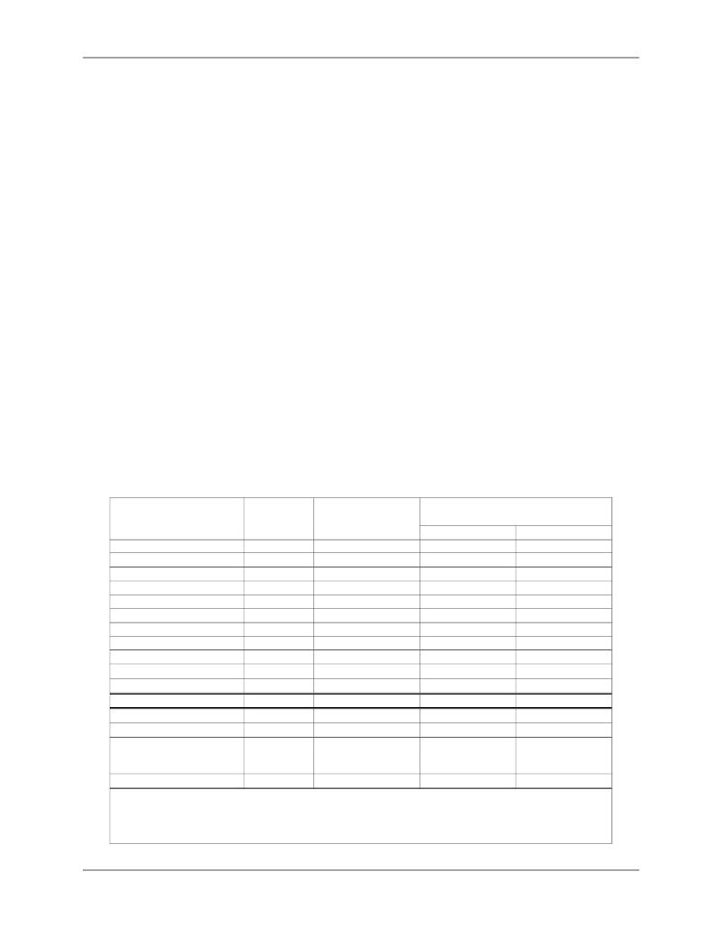
�Table� 1.� Required� CE� Code� and� Settings� for� Local� Sensors�
�I/O� RAM�
�Mnemonic�
�I/O� RAM�
�Location�
�71M6541D/F/G�
�(hex)�
�71M6542F/G�
�(hex)�
�Eq.� 0� or� 1� Eq.� 2�
�FIR_LEN[1:0]�
�ADC_DIV�
�PLL_FAST�
�MUX_DIV[3:0]� 1�
�MUX0_SEL[3:0]�
�MUX1_SEL[3:0]�
�MUX2_SEL[3:0]�
�MUX3_SEL[3:0]�
�RMT_E�
�DIFFA_E�
�DIFFB_E�
�EQU[2:0]�
�CE� Code�
�Equations�
�210C[2:1]�
�2200[5]�
�2200[4]�
�2100[7:4]�
�2105[3:0]�
�2105[7:4]�
�2104[3:0]�
�2104[7:4]�
�2709[3]�
�210C[4]�
�210C[5]�
�2106[7:5]�
�--�
�--�
�1�
�1�
�1�
�3�
�0�
�A�
�2�
�1�
�0�
�1�
�1�
�0� or� 1�
�CE41A01�
�0� or� 1�
�1�
�1�
�1�
�3�
�0�
�A�
�2�
�1�
�0�
�1�
�1�
�0� or� 1�
�CE41A01�
�0� or� 1�
�2�
�0�
�1�
�4�
�0�
�A�
�2�
�9�
�0�
�1�
�1�
�2�
�CE41A04�
�2�
�Current� Sensor� Types�
�--�
�1� Shunt� and� 1� CT�
�or�
�2� CTs�
�1� Shunt� and� 1� CT�
�or�
�2� CTs�
�1� Shunt� and� 1� CT�
�or�
�2� CTs�
�Applicable� Figure�
�--�
����Notes:�
�1� .� MUX_DIV[3:0]� must� be� set� to� 0� while� writing� the� other� RAM� locations� in� this� table.�
�Maxim� updates� the� CE� code� periodically.� Contact� your� local� Maxim� representative� to� obtain� the� latest� CE� code� and�
�the� associated� settings.� The� configuration� presented� in� this� table� is� set� by� the� MPU� demonstration� code� during�
�initialization.�
�Rev� 4�
�相关PDF资料 |
PDF描述 |
|---|---|
| 71M6511-IGT/F | IC ENERGY METER RESIDENT 64-LQFP |
| T95Z476K010ESSL | CAP TANT 47UF 10V 10% 2910 |
| LTC3541EDD#PBF | IC REG DL BCK/LINEAR SYNC 10-DFN |
| MAX16841ASA+T | IC LED DRVR DIM OFFLINE |
| DFN1.25BK | DURA-FLEX 1.25" BLACK 100' |
相关代理商/技术参数 |
参数描述 |
|---|---|
| 71M6541FT-IGT/F | 制造商:Maxim Integrated Products 功能描述:1-PHASE SOC, 64KB FLASH, PRES TEMP SENSOR - Rail/Tube |
| 71M6541FT-IGTR/F | 制造商:Maxim Integrated Products 功能描述:1-PHASE SOC, 64KB FLASH, PRES TEMP SENSOR - Tape and Reel |
| 71M6541G | 制造商:未知厂家 制造商全称:未知厂家 功能描述:71M6541D/71M6541F/71M6541G/71M6542F/71M6542G 是 TeridianTM 的第4 代高集成度单相电表SoC |
| 71M6541G-IGT/F | 功能描述:计量片上系统 - SoC 71M6541G-IGT/F RoHS:否 制造商:Maxim Integrated 核心:80515 MPU 处理器系列:71M6511 类型:Metering SoC 最大时钟频率:70 Hz 程序存储器大小:64 KB 数据 RAM 大小:7 KB 接口类型:UART 可编程输入/输出端数量:12 片上 ADC: 安装风格:SMD/SMT 封装 / 箱体:LQFP-64 封装:Reel |
| 71M6541GT-IGT/F | 功能描述:IC ENERGY METER 64-LQFP 制造商:maxim integrated 系列:Single Converter Technology? 包装:托盘 零件状态:停产 输入阻抗:- 测量误差:0.1% 电压 - I/O 高:2V 电压 - I/O 低:0.8V 电流 - 电源:- 电压 - 电源:3 V ~ 3.6 V 表计类型:单相 工作温度:-40°C ~ 85°C 安装类型:表面贴装 封装/外壳:64-LQFP 供应商器件封装:64-LQFP(10x10) 标准包装:1,000 |
发布紧急采购,3分钟左右您将得到回复。