- 您现在的位置:买卖IC网 > PDF目录16263 > 78P2352-DB-CMI (Maxim Integrated Products)EVAL BOARD 78P235X PDF资料下载
参数资料
| 型号: | 78P2352-DB-CMI |
| 厂商: | Maxim Integrated Products |
| 文件页数: | 26/42页 |
| 文件大小: | 0K |
| 描述: | EVAL BOARD 78P235X |
| 标准包装: | 1 |
| 系列: | * |
第1页第2页第3页第4页第5页第6页第7页第8页第9页第10页第11页第12页第13页第14页第15页第16页第17页第18页第19页第20页第21页第22页第23页第24页第25页当前第26页第27页第28页第29页第30页第31页第32页第33页第34页第35页第36页第37页第38页第39页第40页第41页第42页
78P2352
Dual Channel
OC-3/ STM1-E/ E4 LIU
Page: 32 of 42
2006 Teridian Semiconductor Corporation
Rev. 2.4
ELECTRICAL SPECIFICATIONS (continued)
(Note 1)
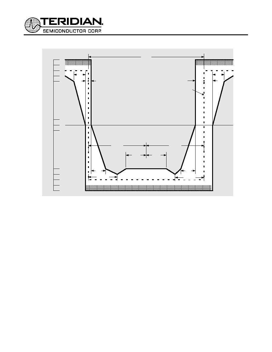
0.60
0.55
0.50
0.45
0.40
0.05
-0.05
-0.50
-0.55
-0.60
-0.45
-0.40
(Note 1)
Nominal
Zero Level
(Note 2)
6.43ns
0.1ns
1ns
1.608ns
1ns
Nominal
Pulse
V
3.215ns
1.2ns
3.215ns
1.608ns
1ns
0.5ns
Note 1 – The maximum “steady state” amplitude should not exceed the 0.55V limit. Overshoots and other transients are permitted to fall into
the shaded area bounded by the amplitude levels 0.55V and 0.6V, provided that they do not exceed the steady state level by more than
0.05V.
Note 2 – For all measurements using these masks, the signal should be AC coupled, using a capacitor of not less than 0.01
F, to the input of
the oscilloscope used for measurements. The nominal zero level for both masks should be aligned with the oscilloscope trace with no input
signal. With the signal then applied, the vertical position of the trace can be adjusted with the objective of meeting the limits of the masks. Any
such adjustment should be the same for both masks and should not exceed
±0.05V. This may be checked by removing the input signal again
and verifying that the trace lies with
±0.05V of the nominal zero level of the masks.
Note 3 – Each pulse in a coded pulse sequence should meet the limits of the relevant mask, irrespective of the state of the preceding or
succeeding pulses, with both pulse masks fixed in the same relation to a common timing reference, i.e. with their nominal start and finish
edges coincident. The masks allow for HF jitter caused by intersymbol interference in the output stage, but not for jitter present in the timing
signal associated with the source of the interface signal. When using an oscilloscope technique to determine pulse compliance with the mask,
it is important that successive traces of the pulses overlay in order to suppress the effects of low frequency jitter. This can be accomplished by
several techniques [e.g. a) triggering the oscilloscope on the measured waveform or b) providing both the oscilloscope and the pulse output
circuits with the same clock signal].
Note 4 – For the purpose of these masks, the rise time and decay time should be measured between –0.4V and 0.4V, and should not exceed
2ns.
Note 5 –The inverse pulse will have the same characteristics, noting that the timing tolerance at the level of the negative and positive
transitions are
± 0.1ns and ±0.5ns respectively.
Figure 14 – Mask of a Pulse corresponding to a binary One in STS-3/STM-1 mode
相关PDF资料 |
PDF描述 |
|---|---|
| EBA28DREH | CONN EDGECARD .125 PCB 56POS |
| EBM24DRMI-S288 | CONN EDGECARD 48POS .156 EXTEND |
| PLE0G821MDO1 | CAP ALUM 820UF 4V 20% RADIAL |
| PLE0J821MDO1 | CAP ALUM 820UF 6.3V 20% RADIAL |
| PLE0E152MDO1 | CAP ALUM 1500UF 2.5V 20% RADIAL |
相关代理商/技术参数 |
参数描述 |
|---|---|
| 78P2352-IEL | 制造商:TERIDIAN 制造商全称:TERIDIAN 功能描述:Dual Channel OC-3/ STM1-E/ E4 LIU |
| 78P2352-IEL/F | 功能描述:接口 - 专用 Dual Ch OC-3/STM1-1e/E4 LIU RoHS:否 制造商:Texas Instruments 产品类型:1080p60 Image Sensor Receiver 工作电源电压:1.8 V 电源电流:89 mA 最大功率耗散: 最大工作温度:+ 85 C 安装风格:SMD/SMT 封装 / 箱体:BGA-59 |
| 78P2352-IELR | 制造商:TERIDIAN 制造商全称:TERIDIAN 功能描述:Dual Channel OC-3/ STM1-E/ E4 LIU |
| 78P2352-IELR/F | 功能描述:IC LIU SDH SONET 2CH 128-LQFP RoHS:是 类别:集成电路 (IC) >> 接口 - 驱动器,接收器,收发器 系列:- 产品培训模块:Lead (SnPb) Finish for COTS Obsolescence Mitigation Program 标准包装:25 系列:- 类型:收发器 驱动器/接收器数:2/2 规程:RS232 电源电压:4.5 V ~ 5.5 V 安装类型:通孔 封装/外壳:16-DIP(0.300",7.62mm) 供应商设备封装:16-PDIP 包装:管件 |
| 78P2352-IGT | 制造商:TERIDIAN 制造商全称:TERIDIAN 功能描述:Dual Channel OC-3/ STM1-E/ E4 LIU |
发布紧急采购,3分钟左右您将得到回复。