参数资料
| 型号: | A42MX09-3VQG100I |
| 厂商: | Microsemi SoC |
| 文件页数: | 35/142页 |
| 文件大小: | 0K |
| 描述: | IC FPGA MX SGL CHIP 14K 100VQFP |
| 标准包装: | 90 |
| 系列: | MX |
| 输入/输出数: | 83 |
| 门数: | 14000 |
| 电源电压: | 3 V ~ 3.6 V,4.5 V ~ 5.5 V |
| 安装类型: | 表面贴装 |
| 工作温度: | -40°C ~ 85°C |
| 封装/外壳: | 100-TQFP |
| 供应商设备封装: | 100-VQFP(14x14) |
第1页第2页第3页第4页第5页第6页第7页第8页第9页第10页第11页第12页第13页第14页第15页第16页第17页第18页第19页第20页第21页第22页第23页第24页第25页第26页第27页第28页第29页第30页第31页第32页第33页第34页当前第35页第36页第37页第38页第39页第40页第41页第42页第43页第44页第45页第46页第47页第48页第49页第50页第51页第52页第53页第54页第55页第56页第57页第58页第59页第60页第61页第62页第63页第64页第65页第66页第67页第68页第69页第70页第71页第72页第73页第74页第75页第76页第77页第78页第79页第80页第81页第82页第83页第84页第85页第86页第87页第88页第89页第90页第91页第92页第93页第94页第95页第96页第97页第98页第99页第100页第101页第102页第103页第104页第105页第106页第107页第108页第109页第110页第111页第112页第113页第114页第115页第116页第117页第118页第119页第120页第121页第122页第123页第124页第125页第126页第127页第128页第129页第130页第131页第132页第133页第134页第135页第136页第137页第138页第139页第140页第141页第142页
40MX and 42MX FPGA Families
Re vi s i on 11
1-9
Power Supply
MX devices are designed to operate in both 5.0V and 3.3V environments. In particular, 42MX devices
can operate in mixed 5.0V/3.3V systems. Table 1-1 describes the voltage support of MX devices.
Power-Up/Down in Mixed-Voltage Mode
When powering up 42MX in mixed voltage mode (VCCA = 5.0 V and VCCI = 3.3 V), VCCA must be
greater than or equal to VCCI throughout the power-up sequence. If VCCI exceeds VCCA during power-
up, one of two things will happen:
The input protection diode on the I/Os will be forward biased
The I/Os will be at logical High
In either case, ICC rises to high levels.
For power-down, any sequence with VCCA and VCCI can be implemented.
Transient Current
Due to the simultaneous random logic switching activity during power-up, a transient current may appear
on the core supply (VCC). Customers must use a regulator for the VCC supply that can source a
minimum of 100 mA for transient current during power-up. Failure to provide enough power can prevent
the system from powering up properly and result in functional failure. However, there are no reliability
concerns, since transient current is distributed across the die instead of confined to a localized spot.
Since the transient current is not due to I/O switching, its value and duration are independent of the
VCCI.
Low Power Mode
42MX devices have been designed with a Low Power Mode. This feature, activated with setting the
special LP pin to HIGH for a period longer than 800 ns, is particularly useful for battery-operated systems
where battery life is a primary concern. In this mode, the core of the device is turned off and the device
consumes minimal power with low standby current. In addition, all input buffers are turned off, and all
outputs and bidirectional buffers are tristated. Since the core of the device is turned off, the states of the
registers are lost. The device must be re-initialized when exiting Low Power Mode. I/Os can be driven
during LP mode, and clock pins should be driven HIGH or LOW and should not float to avoid drawing
current. To exit LP mode, the LP pin must be pulled LOW for over 200 s to allow for charge pumps to
power up, and device initialization will begin.
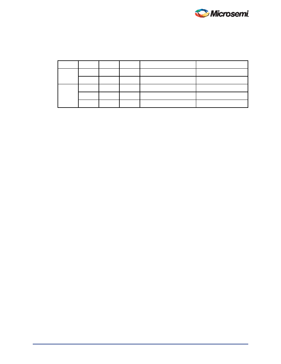
Table 1-1
Voltage Support of MX Devices
Device
VCC
VCCA
VCCI
Maximum Input Tolerance
Nominal Output Voltage
40MX
5.0 V
–
5.5 V
5.0V
3.3 V
–
3.6 V
3.3V
42MX
–
5.0 V
5.5 V
5.0V
–
3.3 V
3.6 V
3.3V
–
5.0 V
3.3 V
5.5 V
3.3V
相关PDF资料 |
PDF描述 |
|---|---|
| A42MX09-3VQ100I | IC FPGA MX SGL CHIP 14K 100VQFP |
| EPF10K30AQC208-2N | IC FLEX 10KA FPGA 30K 208-PQFP |
| EPF10K30AQC208-2 | IC FLEX 10KA FPGA 30K 208-PQFP |
| EPF10K30ATI144-3N | IC FLEX 10KA FPGA 30K 144-TQFP |
| EPF10K30ATI144-3 | IC FLEX 10KA FPGA 30K 144-TQFP |
相关代理商/技术参数 |
参数描述 |
|---|---|
| A42MX09-BG100 | 制造商:ACTEL 制造商全称:Actel Corporation 功能描述:40MX and 42MX FPGA Families |
| A42MX09-BG100ES | 制造商:ACTEL 制造商全称:Actel Corporation 功能描述:40MX and 42MX FPGA Families |
| A42MX09-BG100I | 制造商:ACTEL 制造商全称:Actel Corporation 功能描述:40MX and 42MX FPGA Families |
| A42MX09-BG100M | 制造商:ACTEL 制造商全称:Actel Corporation 功能描述:40MX and 42MX FPGA Families |
| A42MX09-CQ100 | 制造商:ACTEL 制造商全称:Actel Corporation 功能描述:40MX and 42MX FPGA Families |
发布紧急采购,3分钟左右您将得到回复。