- 您现在的位置:买卖IC网 > PDF目录10977 > AD5934YRSZ-REEL7 (Analog Devices Inc)IC CONV 12BIT 250KSPS 16SSOP PDF资料下载
参数资料
| 型号: | AD5934YRSZ-REEL7 |
| 厂商: | Analog Devices Inc |
| 文件页数: | 5/32页 |
| 文件大小: | 0K |
| 描述: | IC CONV 12BIT 250KSPS 16SSOP |
| 产品培训模块: | Direct Digital Synthesis Tutorial Series (1 of 7): Introduction Direct Digital Synthesizer Tutorial Series (7 of 7): DDS in Action Direct Digital Synthesis Tutorial Series (3 of 7): Angle to Amplitude Converter Direct Digital Synthesis Tutorial Series (6 of 7): SINC Envelope Correction Direct Digital Synthesis Tutorial Series (4 of 7): Digital-to-Analog Converter Direct Digital Synthesis Tutorial Series (2 of 7): The Accumulator |
| 标准包装: | 500 |
| 分辨率(位): | 12 b |
| 主 fclk: | 16.776MHz |
| 电源电压: | 2.7 V ~ 5.5 V |
| 工作温度: | -40°C ~ 125°C |
| 安装类型: | 表面贴装 |
| 封装/外壳: | 16-SSOP(0.209",5.30mm 宽) |
| 供应商设备封装: | 16-SSOP |
| 包装: | 带卷 (TR) |
| 配用: | EVAL-AD5934EBZ-ND - BOARD EVALUATION FOR AD5934 |
第1页第2页第3页第4页当前第5页第6页第7页第8页第9页第10页第11页第12页第13页第14页第15页第16页第17页第18页第19页第20页第21页第22页第23页第24页第25页第26页第27页第28页第29页第30页第31页第32页
Data Sheet
AD5934
Rev. C | Page 13 of 32
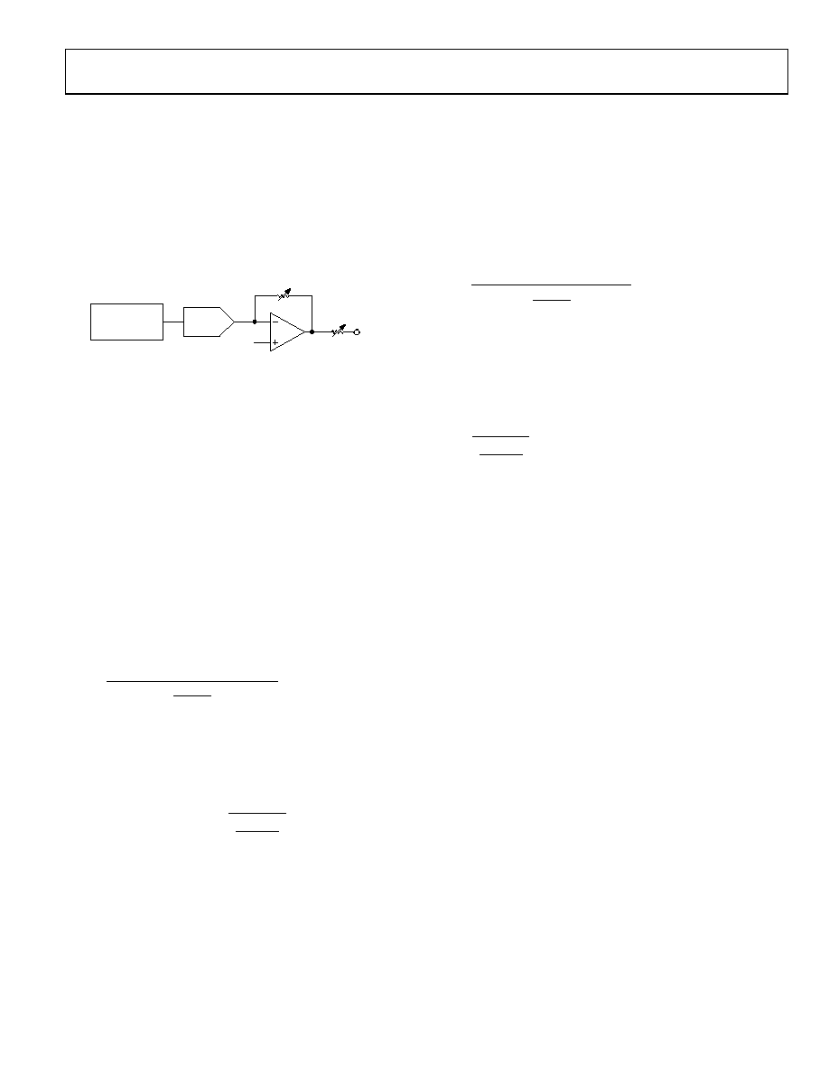
TRANSMIT STAGE
As shown in Figure 16, the transmit stage of the AD5934 is made
up of a 27-bit phase accumulator DDS core that provides the output
excitation signal at a particular frequency. The input to the phase
accumulator is taken from the contents of the start frequency register
(see Register Address 0x82, Register Address 0x83, and Register
Address 0x84). Although the phase accumulator offers 27 bits of
resolution, the start frequency register has the three most significant
bits (MSBs) set to 0 internally; therefore, the user has the ability to
program only the lower 24 bits of the start frequency register.
PHASE
ACCUMULATOR
(27 BITS)
VOUT
ROUT
DAC
R(GAIN)
VBIAS
05325-
034
Figure 16. Transmit Stage
The AD5934 offers a frequency resolution programmable by the
user down to 0.1 Hz. The frequency resolution is programmed via
a 24-bit word loaded serially over the I2C interface to the frequency
increment register.
The frequency sweep is fully described by the programming of
three parameters: the start frequency, the frequency increment,
and the number of increments.
Start Frequency
This is a 24-bit word that is programmed to the on-board RAM
at Register Address 0x82, Register Address 0x83, and Register
Address 0x84 (see the Register Map section). The required code
loaded to the start frequency register is the result of the formula
shown in Equation 1, based on the master clock frequency and the
required start frequency output from the DDS.
27
2
16
×
=
MCLK
Frequency
Start
Output
Required
Code
Frequency
Start
(1)
For example, if the user requires the sweep to begin at 30 kHz and
has a 16 MHz clock signal connected to MCLK, the code that needs
to be programmed is given by
0x3D70A3
2
16
MHz
16
kHz
30
27 =
×
=
Code
Frequency
Start
The user programs the value of 0x3D to Register Address 0x82,
the value 0x70 to Register Address 0x83, and the value 0xA3 to
Register Address 0x84.
Frequency Increment
This is a 24-bit word that is programmed to the on-board RAM at
Register Address 0x85, Register Address 0x86, and Register Address
0x87 (see the Register Map section). The required code loaded to
the frequency increment register is the result of the formula shown in
Equation 2, based on the master clock frequency and the required
increment frequency output from the DDS.
27
2
16
×
=
MCLK
Increment
Frequency
Required
Code
Increment
Frequency
(2)
For example, if the user requires the sweep to have a resolution of
10 Hz and has a 16 MHz clock signal connected to MCLK, the code
that needs to be programmed is given by
0x00053E
16
MHz
16
Hz
10
≡
=
Code
Increment
Frequency
The user programs the value 0x00 to Register Address 0x85, the
value 0x05 to Register Address 0x86, and the value 0x3E to
Register Address 0x87.
Number of Increments
This is a 9-bit word that represents the number of frequency
points in the sweep. The number is programmed to the on-board
RAM at Register Address 0x88 and Register Address 0x89 (see the
Register Map section). The maximum number of points that can
be programmed is 511.
For example, if the sweep needs 150 points, the user programs
the value 0x00 to Register Address 0x88 and the value 0x96 to
Register Address 0x89.
Once the three parameter values are programmed, the sweep is
initiated by issuing a start frequency sweep command to the
control register at Register Address 0x80 and Register Address
0x81 (see the Register Map section). Bit D2 in the status register
(Register Address 0x8F) indicates the completion of the frequency
measurement for each sweep point. Incrementing to the next
frequency sweep point is under the control of the user. The measured
result is stored in the two register groups that follow: 0x94, 0x95
(real data) and 0x96, 0x97 (imaginary data) that should be read
before issuing an increment frequency command to the control
register to move to the next sweep point. There is the facility to
repeat the current frequency point measurement by issuing a
repeat frequency command to the control register. This has the
benefit of allowing the user to average successive readings. When
the frequency sweep has completed all frequency points, Bit D3 in
the status register is set, indicating the completion of the sweep.
Once this bit is set, further increments are disabled.
相关PDF资料 |
PDF描述 |
|---|---|
| VE-B1D-IX-B1 | CONVERTER MOD DC/DC 85V 75W |
| AD9833BRMZ-REEL7 | IC WAVEFORM GEN PROG 10MSOP |
| VE-B1D-IW-B1 | CONVERTER MOD DC/DC 85V 100W |
| MCF51AC256BCFUE | MCU 32BIT 256K FLASH 64-QFP |
| AD9833BRMZ-REEL | IC WAVEFORM GEN PROG 10MSOP |
相关代理商/技术参数 |
参数描述 |
|---|---|
| AD594 | 制造商:AD 制造商全称:Analog Devices 功能描述:Monolithic Thermocouple Amplifiers with Cold Junction Compensation |
| AD594A | 制造商:AD 制造商全称:Analog Devices 功能描述:Monolithic Thermocouple Amplifiers with Cold Junction Compensation |
| AD594AD | 制造商:Analog Devices 功能描述:Temp Sensor Analog 14-Pin TO-116 制造商:Rochester Electronics LLC 功能描述:THERMOCOUPLER AMPLIFIER - Bulk 制造商:Analog Devices 功能描述:Special Function IC Package/Case:TO-116 |
| AD594AD/+ | 制造商:Rochester Electronics LLC 功能描述:- Bulk |
| AD594ADZ | 功能描述:IC THERMOCOUPLE INSTR AMP 14CDIP RoHS:是 类别:集成电路 (IC) >> PMIC - 热管理 系列:- 标准包装:3,000 系列:- 功能:温度开关 传感器类型:内部 感应温度:85°C 分界点 精确度:±6°C(最小值) 拓扑:ADC(三角积分型),比较器,寄存器库 输出类型:开路漏极 输出警报:是 输出风扇:是 电源电压:2.7 V ~ 5.5 V 工作温度:-55°C ~ 125°C 安装类型:表面贴装 封装/外壳:SC-74A,SOT-753 供应商设备封装:SOT-23-5 包装:带卷 (TR) 其它名称:ADT6501SRJZP085RL7-ND |
发布紧急采购,3分钟左右您将得到回复。