- 您现在的位置:买卖IC网 > PDF目录373890 > AD6622S (Analog Devices, Inc.) Four-Channel, 75 MSPS Digital Transmit Signal Processor TSP PDF资料下载
参数资料
| 型号: | AD6622S |
| 厂商: | Analog Devices, Inc. |
| 英文描述: | Four-Channel, 75 MSPS Digital Transmit Signal Processor TSP |
| 中文描述: | 4通道,75 MSPS的数字传输信号处理器判刑 |
| 文件页数: | 12/28页 |
| 文件大小: | 242K |
| 代理商: | AD6622S |
第1页第2页第3页第4页第5页第6页第7页第8页第9页第10页第11页当前第12页第13页第14页第15页第16页第17页第18页第19页第20页第21页第22页第23页第24页第25页第26页第27页第28页
AD6622
–12–
REV. 0
1. Select the Impulse Response Length (N
RCF
) and the Inter-
polation Factor (L
RCF
). The Impulse Response Length
(N
RCF
) is limited in three ways: by the available calculation
time, by the data memory size (DMEM), and by the coef
fi
-
cient memory size (CMEM). The equation below shows
that N
RCF
is limited to the minimum of these three conditions.
Time
Restriction
↓
2
↑
DMEM
Restriction
where:
L
= L
RCF
×
L
CIC5
×
L
CIC2
2. The interpolation rate (L
RCF
) may be any integer of N
RCF
ranging from 1 to 128, while meeting the above equation.
Most
fi
lter designs can be optimized by choosing the small-
est L
RCF
that does not compromise the image rejection of
the subsequent CIC
fi
lter. The quality of an interpolating
fi
lter is a strong function of the N
RCF
/L
RCF
ratio and a weaker
function of N
RCF
. The best
fi
lters are usually achieved by
maximizing N
RCF
/L
RCF
(no larger than 16) and then increasing
both N
RCF
and L
RCF
by the same ratio until the
fi
lter becomes
time or CMEM limited.
3. Once N
RCF
and L
RCF
are selected, Channel Register 0x0A
is programmed to N
RCF
–
1, and Channel Register 0x0C is
programmed to N
RCF
/L
RCF
–
1.
4. Determine the Impulse Response. The impulse response
relative to the RCF output rate can be calculated using ordi-
nary FIR design techniques. In most cases, it is desirable to
precompensate the inband frequency roll-off of the CIC
fi
l-
ter that follows. There are no symmetry requirements, so the
RCF can also be used for static phase equalization. The
impulse response must be quantized to 16-bit two
’
s comple-
ment numbers for the CMEM. The channel center gain and
worst-case peak can be calculated for each of the L
RCF
phases
(p) according to the equations below. A RCF coarse scale
factor (g) that ranges between 0 and 3 is provided to limit
the gain without excessive loss of resolution in the CMEM.
The coarse scale factor is located in Channel Register 0x0D.
CMEM
Restriction
↓
N
L
L
RCF
RCF
≤
×
min
,
,
16
128
(6)
ChannelCenterGain
h k
[
L
p
p
g
RCF
k
N
L
RCF
RCF
∑
=
=
×
×
+
2
0
1
]
–
(7)
5. The channel center gain is the response to a constant full-
scale input at every output phase. The summation is split
into phases because the interpolation of the data insures that
only N
RCF
/L
RCF
coef
fi
cients can be active for any single output.
For L
RCF
= 1, there is only one phase and the channel center
gain is the simple sum of all the coef
fi
cients, scaled by 2
–
g
. If
the channel center gain is not the same for every value of p,
some or all of the images of the channel center will be
imperfectly rejected by the RCF.
WorstCasePeak
|h k
L
p
p
g
RCF
k
N
L
RCF
RCF
∑
=
=
×
×
+
2
0
1
]|
–
(8)
6. The worst-case peak is calculated similarly to the channel
center gain, except that the input sequence swings from full-
scale positive to full-scale negative to match the polarity of the
coef
fi
cient by which it will be multiplied, so that each prod-
uct is positive. This results in a maximal that must be less
than one to guarantee no possibility of wrapping. Note that
when L
RCF
is greater than one, each phase may produce its
worst-case peak in response to a different input sequence.
7. Programming DMEM and CMEM. The DMEM must be
initialized to all zeros to avoid any unpredictable start-up
transients since a reset does not clear the memory. The
impulse response h[n] must be reordered by phase for the
CMEM as shown in the code below. Several
fi
lters with
impulse lengths that total less than 128 can be programmed
into the CMEM simultaneously and selected later using the
RCF offset pointer (O
RCF
) which is set by Channel Register
0x0B.
/
*
Reorder Fir Coefficients for AD6622 CMEM
*
/
for (p=0; p<L_RCF; p++)
for (k=0; k<N_RCF/L_RCF; k++)
CMEM[O_RCF + p*N_RCF/L_RCF + k] = C[k*L_RCF +p];
/
*
End of routine
*
/
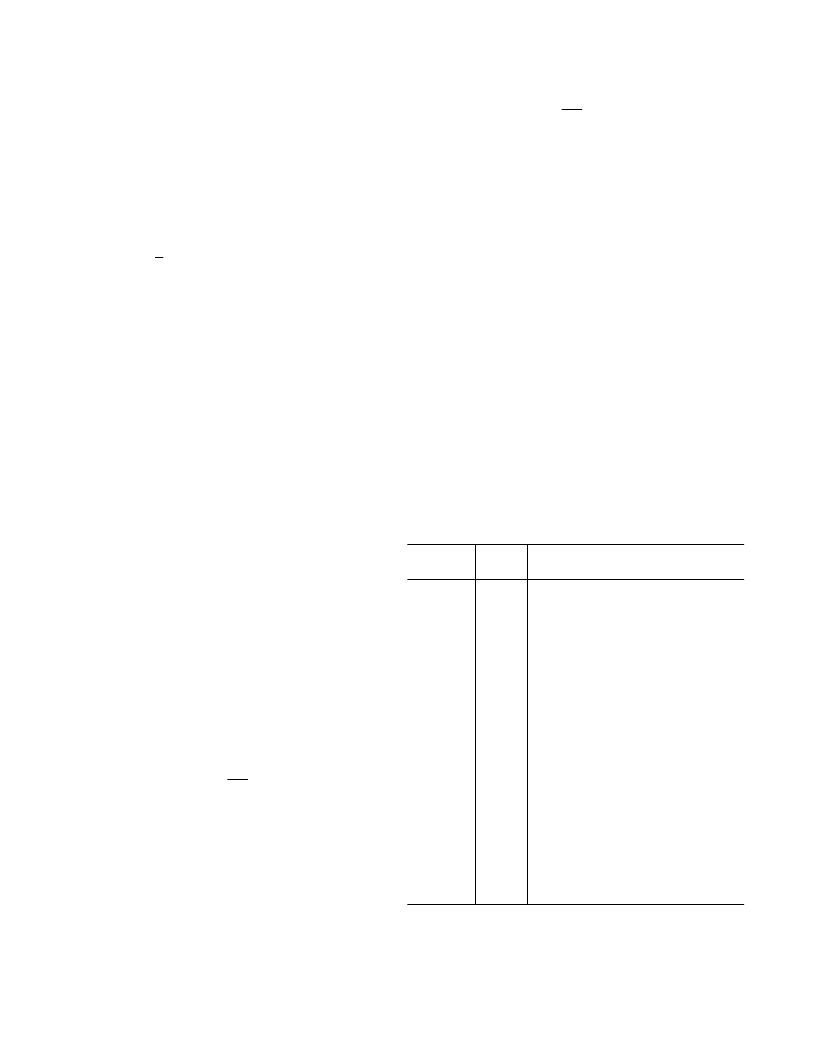
Table I. RCF Control Registers
Channel
Address
Bit
Width
Description
0x0A
8
7: Reserved (Must Be Written to 0)
6
–
0: N
RCF
–
1
7: Reserved (Must Be Written to 0)
6
–
0: O
RCF
7
–
6: Reserved
5
–
4: Reserved (Must Be Written to 0)
3
–
0: N
RCF
/L
RCF
–
1
7
–
6: RCF Coarse Scale:
00 = 0 dB
01 =
–
6 dB
10 =
–
12 dB
11 =
–
18 dB
5: Reserved (Must Be Written to 0)
4
–
0: Serial Clock Divider
15
–
0: Reserved
15
–
0: Reserved
15
–
0: Reserved (Must Be Written to 0)
15
–
0: Reserved (Must Be Written to 0)
15
–
0: Data Memory (DMEM)
15
–
0: Coef
fi
cient Memory (CMEM)
0x0B
8
0x0C
8
0x0D
8
0x0E
0x0F
0x10
0x11
0x20
–
0x3F
0x80
–
0xFF
16
16
16
16
16
16
相关PDF资料 |
PDF描述 |
|---|---|
| AD6622 | Four-Channel, 75 MSPS Digital Transmit Signal Processor TSP |
| AD6623 | 4-Channel, 104 MSPS Digital Transmit Signal Processor TSP |
| AD6623ABC | 4-Channel, 104 MSPS Digital Transmit Signal Processor TSP |
| AD6623AS | 4-Channel, 104 MSPS Digital Transmit Signal Processor TSP |
| AD6623PCB | 4-Channel, 104 MSPS Digital Transmit Signal Processor TSP |
相关代理商/技术参数 |
参数描述 |
|---|---|
| AD6622S/PCB | 制造商:AD 制造商全称:Analog Devices 功能描述:Four-Channel, 75 MSPS Digital Transmit Signal Processor TSP |
| AD6623 | 制造商:Analog Devices 功能描述: |
| AD6623ABC | 制造商:Analog Devices 功能描述:Signal Processor 196-Pin CSP-BGA 制造商:Rochester Electronics LLC 功能描述:4 CHANNEL, 104 MSPS DIGITAL TSP - Bulk |
| AD6623ABCZ | 制造商:Analog Devices 功能描述:Signal Processor 196-Pin CSP-BGA |
| AD6623AS | 制造商:Analog Devices 功能描述:Signal Processor 128-Pin MQFP 制造商:Rochester Electronics LLC 功能描述:4 CHANNEL, 104 MSPS DIGITAL TSP - Bulk |
发布紧急采购,3分钟左右您将得到回复。