参数资料
| 型号: | AD6623ASZ |
| 厂商: | Analog Devices Inc |
| 文件页数: | 14/48页 |
| 文件大小: | 0K |
| 描述: | IC TSP 4CHAN 104MSPS 128MQFP |
| 标准包装: | 1 |
| 应用: | 传输信息处理器 |
| 接口: | 串行 |
| 封装/外壳: | 128-BFQFP |
| 供应商设备封装: | 128-MQFP(14x20) |
| 包装: | 托盘 |
| 安装类型: | 表面贴装 |
第1页第2页第3页第4页第5页第6页第7页第8页第9页第10页第11页第12页第13页当前第14页第15页第16页第17页第18页第19页第20页第21页第22页第23页第24页第25页第26页第27页第28页第29页第30页第31页第32页第33页第34页第35页第36页第37页第38页第39页第40页第41页第42页第43页第44页第45页第46页第47页第48页
REV. A
AD6623
–21–
All of these phase locations are represented in rectangular coor-
dinates by only four unique magnitudes in the positive and negative
directions. These four values are read from four channel registers
that are programmed according to the following table, which
gives the generic formulas and a specific example. The example
is notable because it is only 0.046 dB below full-scale and the
16-bit quantization is so benign at that magnitude, that the rms
error is better than –122 dBc. It is also worth noting that because
none of the phases are aligned with the axes, magnitudes slightly
beyond 0.16 dB above full-scale are achievable.
Table VI. Program Registers
Channel
Register
Magnitude M
Magnitude E 0x7F53
0x12
M 3 cos( /16)
0x7CE1
0x13
M 3 cos(3 /16)
0x69DE
0x14
M 3 cos(5 /16)
0x46BD
0x15
M 3 cos(7 /16)
0x18D7
Using the four channel registers from the preceding table, the PSK
Modulator assembles the 16 phases according to Table VII.
Table VII. PSK Modulator Phase
Phase
I Value
Q Value
0
0x12
0x15
1
0x13
0x14
2
0x14
0x13
3
0x15
0x12
4
–0x15
+0x12
5
–0x14
+0x13
6
–0x13
+0x14
7
–0x12
+0x15
8
–0x12
–0x15
9
–0x13
–0x14
10
–0x14
–0x13
11
–0x15
–0x12
12
+0x15
–0x12
13
+0x14
–0x13
14
+0x13
–0x14
15
+0x12
–0x15
The following three sections show how the phase values are
created for each PSK modulation mode.
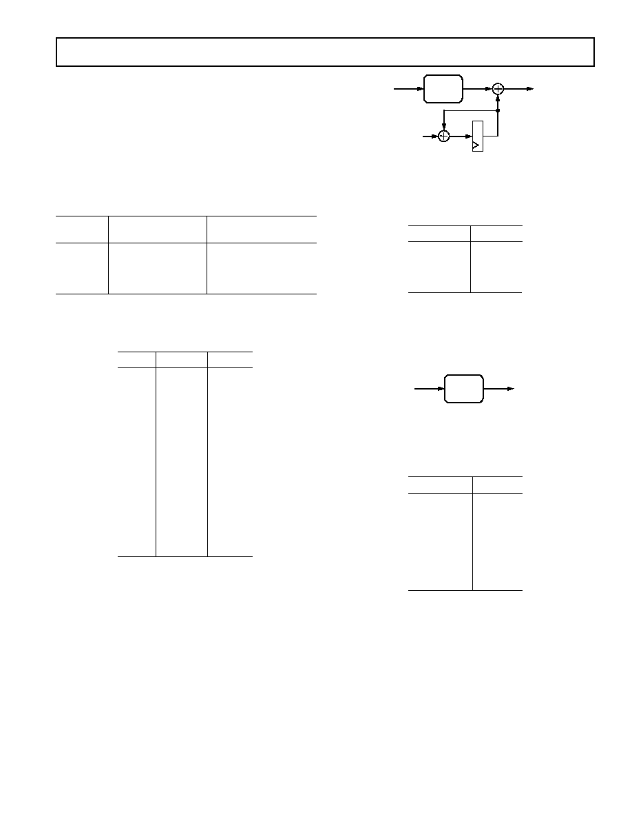
/4-DQPSK Modulation
IS-136 compliant
/4-DQPSK modulation is selected by setting
the channel register 0xn0C: 6–4 to 001b. The phase word is
calculated according to the following diagram. The two LSBs of
the serial input word update the payload bits once per symbol.
The QPSK Mapper creates a data dependent static phase word
(Sph) which is added to a time dependent rotating phase word
(Rph). The Rph starts at zero when the RCF is reset or switches
modes via a sync pulse. Otherwise, the Rph increments by two
on every symbol.
SERIAL
QPSK
MAPPER
SPH
[1:0]
[3:0]
PHASE
[3:0]
RPH
2
Figure 22. QPSK Mapper
The Sph word is calculated by the QPSK Mapper according to
the following truth table.
Table VIII. QPSK Mapper Truth Table
Serial [1:0]
Sph [3:0]
00b
0
01b
4
11b
8
10b
12
8-PSK Modulation
IS-136+ compliant 8-PSK modulation is selected by setting the
channel register 0xn0C: 6–4 to 101b. The Phase word is calcu-
lated according to the following diagram. The three LSBs of the
serial input word update the payload bits once per symbol.
SERIAL
8-PSK
MAPPER
[2:0]
PHASE
[3:0]
Figure 23. 8-PSK Mapper
The Phase word is calculated by the 8-PSK Mapper according
to the following truth table:
Table IX. 8-PSK Mapper Truth Table
Serial [2:0]
Sph [3:0]
111b
0
011b
2
010b
4
000b
6
001b
8
101b
10
100b
12
110b
14
3 /8-8-PSK Modulation
EDGE compliant 3 /8-8-PSK modulation is selected by setting the
channel register 0xn0C: 6–4 to 110b. The phase word is calculated
according to the following diagram. The three LSBs of the serial
input word update the payload bits once per symbol. The 8-PSK
Mapper creates a data-dependent static phase word (Sph) which is
added to a time-dependent rotating phase word (Rph). The 8-PSK
Mapper operates exactly as described in the preceding 8-PSK
Modulation section. The Rph starts at zero when the RCF is reset
or switches modes via a sync pulse. Otherwise, the Rph increments
by three on every symbol.
相关PDF资料 |
PDF描述 |
|---|---|
| AD6641BCPZRL7-500 | IC IF RCVR 11BIT 200MSPS 56LFCSP |
| AD664BJ | IC DAC 12BIT QUAD MONO 44-JLCC |
| AD667BD | IC DAC 12BIT W/BUFF LTCH 28-CDIP |
| AD669BN | IC DAC 16BIT MONO VREF 28-DIP |
| AD693AE | IC SGNL COND 4-20MA TX 20-CLCC |
相关代理商/技术参数 |
参数描述 |
|---|---|
| AD6623BC/PCB | 制造商:AD 制造商全称:Analog Devices 功能描述:4-Channel, 104 MSPS Digital Transmit Signal Processor TSP |
| AD6623PCB | 制造商:AD 制造商全称:Analog Devices 功能描述:4-Channel, 104 MSPS Digital Transmit Signal Processor TSP |
| AD6623S/PCB | 制造商:Analog Devices 功能描述:4-CH, 104 MSPS DGTL TRANSMIT SGNL PROCESSOR (TSP) 28SOIC - Bulk |
| AD6624 | 制造商:AD 制造商全称:Analog Devices 功能描述:Four-Channel, 80 MSPS Digital Receive Signal Processor (RSP) |
| AD6624A | 制造商:AD 制造商全称:Analog Devices 功能描述:Four-Channel, 100 MSPS Digital Receive Signal Processor (RSP) |
发布紧急采购,3分钟左右您将得到回复。