- 您现在的位置:买卖IC网 > PDF目录10516 > AD677KNZ (Analog Devices Inc)IC ADC 16BIT SAMPLING 16DIP PDF资料下载
参数资料
| 型号: | AD677KNZ |
| 厂商: | Analog Devices Inc |
| 文件页数: | 2/16页 |
| 文件大小: | 0K |
| 描述: | IC ADC 16BIT SAMPLING 16DIP |
| 标准包装: | 1 |
| 位数: | 16 |
| 采样率(每秒): | 100k |
| 数据接口: | DSP,串行 |
| 转换器数目: | 1 |
| 功率耗散(最大): | 480mW |
| 电压电源: | 模拟和数字,双 ± |
| 工作温度: | 0°C ~ 70°C |
| 安装类型: | 通孔 |
| 封装/外壳: | 16-DIP(0.300",7.62mm) |
| 供应商设备封装: | 16-PDIP |
| 包装: | 管件 |
| 输入数目和类型: | 1 个单端,双极 |
| 配用: | AD677-EB-ND - BOARD EVAL SAMPLING ADC AD677 |
AD677
REV. A
–10–
Additionally, it is beneficial to have large capacitors (>47
F)
located at the point where the power connects to the PCB with
10
F capacitors located in the vicinity of the ADC to further
reduce low frequency ripple. In systems that will be subjected to
particularly harsh environmental noise, additional decoupling
may be necessary. RC-filtering on each power supply combined
with dedicated voltage regulation can substantially decrease
power supply ripple effects (this is further detailed in Figure 7).
BOARD LAYOUT
Designing with high resolution data converters requires careful
attention to board layout. Trace impedance is a significant issue.
A 1.22 mA current through a 0.5
trace will develop a voltage
drop of 0.6 mV, which is 4 LSBs at the 16-bit level for a 10 V
full-scale span. In addition to ground drops, inductive and capaci-
tive coupling need to be considered, especially when high accu-
racy analog signals share the same board with digital signals.
Analog and digital signals should not share a common return
path. Each signal should have an appropriate analog or digital
return routed close to it. Using this approach, signal loops en-
close a small area, minimizing the inductive coupling of noise.
Wide PC tracks, large gauge wire, and ground planes are highly
recommended to provide low impedance signal paths. Separate
analog and digital ground planes are also desirable, with a single
interconnection point at the AD677 to minimize interference
between analog and digital circuitry. Analog signals should be
routed as far as possible from digital signals and should cross
them, if at all, only at right angles. A solid analog ground plane
around the AD677 will isolate it from large switching ground
currents. For these reasons, the use of wire wrap circuit con-
struction will not provide adequate performance; careful printed
circuit board construction is preferred.
GROUNDING
The AD677 has three grounding pins, designated ANALOG
GROUND (AGND), DIGITAL GROUND (DGND) and
ANALOG GROUND SENSE (AGND SENSE). The analog
ground pin is the “high quality” ground reference point for the
device, and should be connected to the analog common point in
the system.
AGND SENSE is intended to be connected to the input signal
ground reference point. This allows for slight differences in level
between the analog ground point in the system and the input
signal ground point. However no more than 100 mV is recom-
mended between the AGND and the AGND SENSE pins for
specified performance.
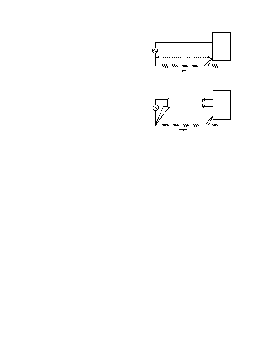
Using AGND SENSE to remotely sense the ground potential of
the signal source can be useful if the signal has to be carried
some distance to the A/D converter. Since all IC ground cur-
rents have to return to the power supply and no ground leads
are free from resistance and inductance, there are always some
voltage differences from one ground point in a system to another.
Over distance this voltage difference can easily amount to sev-
eral LSBs (in a 10 V input span, 16-bit system each LSB is
about 0.15 mV). This would directly corrupt the A/D input sig-
nal if the A/D measures its input with respect to power ground
(AGND) as shown in Figure 5a. To solve this problem the
AD677 offers an AGND SENSE pin. Figure 5b shows how the
AGND SENSE can be used to eliminate the problem in Figure
5a. Figure 5b also shows how the signal wires should be
VIN
AGND
SOURCE
VS
GROUND LEAD
IGROUND > 0
TO POWER
SUPPLY GND
AD677
V
Figure 5a. Input to the A/D is Corrupted by IR Drop in
Ground Leads: VIN = VS + V.
VIN
AGND
SENSE
AGND
SOURCE
VS
SHIELDED CABLE
GROUND LEAD
I
GROUND > 0
TO POWER
SUPPLY GND
AD677
Figure 5b. AGND SENSE Eliminates the Problem in
Figure 5a.
shielded in a noisy environment to avoid capacitive coupling. If
inductive (magnetic) coupling is expected to be dominant such
as where motors are present, twisted-pair wires should be used
instead.
The digital ground pin is the reference point for all of the digital
signals that operate the AD677. This pin should be connected
to the digital common point in the system. As Figure 4 illus-
trated, the analog and digital grounds should be connected
together at one point in the system, preferably at the AD677.
VOLTAGE REFERENCE
The AD677 requires the use of an external voltage reference.
The input voltage range is determined by the value of the refer-
ence voltage; in general, a reference voltage of n volts allows an
input range of
±n volts. The AD677 is specified for a voltage
reference between +5 V and +10 V. A 10 V reference will typi-
cally require support circuitry operated from
±15 V supplies; a
5.0 V reference may be used with
±12 V supplies. Signal-to-
noise performance is increased proportionately with input signal
range (see Figure 12). In the presence of a fixed amount of sys-
tem noise, increasing the LSB size (which results from increas-
ing the reference voltage) will increase the effective S/(N+D)
performance. Figure 11 illustrates S/(N+D) as a function of ref-
erence voltage. In contrast, dc accuracy will be optimal at lower
reference voltage values (such as 5 V) due to capacitor nonlin-
earity at higher voltage values.
During a conversion, the switched capacitor array of the AD677
presents a dynamically changing current load at the voltage ref-
erence as the successive-approximation algorithm cycles through
various choices of capacitor weighting. (See the following sec-
tion “Analog Input” for a detailed discussion of the VREF input
characteristics.) The output impedance of the reference circuitry
must be low so that the output voltage will remain sufficiently
constant as the current drive changes. In some applications, this
may require that the output of the voltage reference be buffered
by an amplifier with low impedance at relatively high frequen-
cies. In choosing a voltage reference, consideration should be
相关PDF资料 |
PDF描述 |
|---|---|
| VI-J22-MY-F2 | CONVERTER MOD DC/DC 15V 50W |
| UP050B821K-B-B | CAP CER 820PF 50V 10% AXIAL |
| VI-JWB-MY-F2 | CONVERTER MOD DC/DC 95V 50W |
| MAX3033ECUE+ | IC RS-422 TRANSMIT QUAD 16TSSOP |
| MS3110P12-10P | CONN RCPT 10POS WALL MNT W/PINS |
相关代理商/技术参数 |
参数描述 |
|---|---|
| AD677KR | 功能描述:IC ADC 16BIT 100KSPS 28-SOIC RoHS:否 类别:集成电路 (IC) >> 数据采集 - 模数转换器 系列:- 标准包装:1 系列:- 位数:14 采样率(每秒):83k 数据接口:串行,并联 转换器数目:1 功率耗散(最大):95mW 电压电源:双 ± 工作温度:0°C ~ 70°C 安装类型:通孔 封装/外壳:28-DIP(0.600",15.24mm) 供应商设备封装:28-PDIP 包装:管件 输入数目和类型:1 个单端,双极 |
| AD677KR-REEL | 功能描述:IC ADC 16BIT SAMPLING 28-SOIC RoHS:否 类别:集成电路 (IC) >> 数据采集 - 模数转换器 系列:- 标准包装:1 系列:- 位数:14 采样率(每秒):83k 数据接口:串行,并联 转换器数目:1 功率耗散(最大):95mW 电压电源:双 ± 工作温度:0°C ~ 70°C 安装类型:通孔 封装/外壳:28-DIP(0.600",15.24mm) 供应商设备封装:28-PDIP 包装:管件 输入数目和类型:1 个单端,双极 |
| AD677KRZ | 功能描述:IC ADC 16BIT 100KSPS 28-SOIC RoHS:是 类别:集成电路 (IC) >> 数据采集 - 模数转换器 系列:- 标准包装:1 系列:- 位数:14 采样率(每秒):83k 数据接口:串行,并联 转换器数目:1 功率耗散(最大):95mW 电压电源:双 ± 工作温度:0°C ~ 70°C 安装类型:通孔 封装/外壳:28-DIP(0.600",15.24mm) 供应商设备封装:28-PDIP 包装:管件 输入数目和类型:1 个单端,双极 |
| AD677KRZ-REEL | 功能描述:IC ADC 16BIT 100KSPS 28-SOIC RoHS:是 类别:集成电路 (IC) >> 数据采集 - 模数转换器 系列:- 标准包装:1 系列:- 位数:14 采样率(每秒):83k 数据接口:串行,并联 转换器数目:1 功率耗散(最大):95mW 电压电源:双 ± 工作温度:0°C ~ 70°C 安装类型:通孔 封装/外壳:28-DIP(0.600",15.24mm) 供应商设备封装:28-PDIP 包装:管件 输入数目和类型:1 个单端,双极 |
| AD677TD | 制造商:未知厂家 制造商全称:未知厂家 功能描述:MICROCIRCUIT, DIGITAL-LINEAR, FAST, SERIAL, 16-BIT, A/D CONVERTER, MULTICHIP SILICON |
发布紧急采购,3分钟左右您将得到回复。