参数资料
| 型号: | AD7840KNZ |
| 厂商: | Analog Devices Inc |
| 文件页数: | 15/16页 |
| 文件大小: | 0K |
| 描述: | IC DAC 14BIT LC2MOS VOUT 24-DIP |
| 产品培训模块: | Data Converter Fundamentals DAC Architectures |
| 标准包装: | 15 |
| 设置时间: | 2.5µs |
| 位数: | 14 |
| 数据接口: | 串行,并联 |
| 转换器数目: | 1 |
| 电压电源: | 双 ± |
| 功率耗散(最大): | 100mW |
| 工作温度: | 0°C ~ 70°C |
| 安装类型: | 通孔 |
| 封装/外壳: | 24-DIP(0.300",7.62mm) |
| 供应商设备封装: | 24-PDIP |
| 包装: | 管件 |
| 输出数目和类型: | 1 电压,双极 |
| 采样率(每秒): | 400k |
AD7840
REV. B
–8–
As in the parallel mode, the LDAC signal controls the loading
of data to the DAC latch. Normally, data is loaded to the DAC
latch on the falling edge of LDAC. However, if LDAC is held
low, then serial data is loaded to the DAC latch on the sixteenth
falling edge of SCLK. If LDAC goes low during the transfer of
serial data to the input latch, no DAC latch update takes place
on the falling edge of LDAC. If LDAC stays low until the serial
transfer is completed, then the update takes place on the six-
teenth falling edge of SCLK. If LDAC returns high before the
serial data transfer is completed, no DAC latch update takes
place. Figure 9 shows the simplified serial input control logic for
the AD7840.
Figure 9. AD7840 Simplified Serial Input Control Logic
AD7840 DYNAMIC SPECIFICATIONS
The AD7840 is specified and 100% tested for dynamic perfor-
mance specifications as well as traditional dc specifications such
as integral and differential nonlinearity. These ac specifications
are required for the signal processing applications such as
speech synthesis, servo control and high speed modems. These
applications require information on the DAC’s effect on the
spectral content of the signal it is creating. Hence, the param-
eters for which the AD7840 is specified include signal-to-noise
ratio, harmonic distortion and peak harmonics. These terms are
discussed in more detail in the following sections.
Signal-to-Noise Ratio (SNR)
SNR is the measured signal-to-noise ratio at the output of the
DAC. The signal is the rms magnitude of the fundamental.
Noise is the rms sum of all the nonfundamental signals up to
half the sampling frequency (fs/2) excluding dc. SNR is depen-
dent upon the number of quantization levels used in the digiti-
zation process; the more levels, the smaller the quantization
noise. The theoretical signal to noise ratio for a sine wave out-
put is given by
SNR = (6.02N + 1.76) dB
(1)
where N is the number of bits. Thus for an ideal 14-bit con-
verter, SNR = 86 dB.
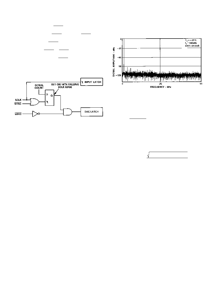
Figure 10 shows a typical 2048 point Fast Fourier Transform
(FFT) plot of the AD7840KN with an output frequency of
1 kHz and an update rate of 100 kHz. The SNR obtained from
this graph is 81.8 dB. It should be noted that the harmonics are
taken into account when calculating the SNR.
Figure 10. AD7840 FFT Plot
Effective Number of Bits
The formula given in (1) relates the SNR to the number of bits.
Rewriting the formula, as in (2) it is possible to get a measure of
performance expressed in effective number of bits (N).
N
= SNR 1.76
6.02
(2)
The effective number of bits for a device can be calculated
directly from its measured SNR.
Harmonic Distortion
Harmonic distortion is the ratio of the rms sum of harmonics to
the fundamental. For the AD7840, total harmonic distortion
(THD) is defined as
THD
= 20 log
V
2
2 +V
3
2 +V
4
2 +V
5
2 +V
6
2
V
1
where V1 is the rms amplitude of the fundamental and V2, V3,
V4, V5 and V6 are the rms amplitudes of the second through the
sixth harmonic. The THD is also derived from the 2048-point
FFT plot.
Peak Harmonic or Spurious Noise
Peak harmonic or spurious noise is defined as the ratio of the
rms value of the next largest component in the DAC output
spectrum (up to fs/2 and excluding dc) to the rms value of the
fundamental. Normally, the value of this specification will be
determined by the largest harmonic in the spectrum, but for
parts where the harmonics are buried in the noise floor the peak
will be a noise peak.
Testing the AD7840
A simplified diagram of the method used to test the dynamic
performance specifications is outlined in Figure 11. Data is
loaded to the AD7840 under control of the microcontroller and
associated logic at a 100 kHz update rate. The output of the
AD7840 is applied to a ninth order, 50 kHz, low-pass filter. The
output of the filter is in turn applied to a 16-bit accurate digi-
tizer. This digitizes the signal and the microcontroller generates
an FFT plot from which the dynamic performance of the
AD7840 can be evaluated.
相关PDF资料 |
PDF描述 |
|---|---|
| AD7248AAP | IC DAC 12BIT W/REF 28-PLCC |
| AD5570WRSZ-REEL | IC DAC 16BIT SERIAL IN 16SSOP |
| AD5544ARSZ-REEL7 | IC DAC 16BIT QUAD SRL 28SSOP |
| AD7228ACPZ-REEL | IC DAC 8BIT OCTAL W/AMP 28-PLCC |
| AD7228ACRZ-REEL | IC DAC 8BIT OCTAL W/AMP 24SOIC |
相关代理商/技术参数 |
参数描述 |
|---|---|
| AD7840KP | 功能描述:IC DAC 14BIT LOW PWR 5V 28-PLCC RoHS:否 类别:集成电路 (IC) >> 数据采集 - 数模转换器 系列:- 产品培训模块:Data Converter Fundamentals DAC Architectures 标准包装:750 系列:- 设置时间:7µs 位数:16 数据接口:并联 转换器数目:1 电压电源:双 ± 功率耗散(最大):100mW 工作温度:0°C ~ 70°C 安装类型:表面贴装 封装/外壳:28-LCC(J 形引线) 供应商设备封装:28-PLCC(11.51x11.51) 包装:带卷 (TR) 输出数目和类型:1 电压,单极;1 电压,双极 采样率(每秒):143k |
| AD7840KP-REEL | 功能描述:14 Bit Digital to Analog Converter 1 28-PLCC (11.51x11.51) 制造商:analog devices inc. 系列:- 包装:带卷(TR) 零件状态:上次购买时间 位数:14 数模转换器数:1 建立时间:4μs 输出类型:Voltage - Buffered 差分输出:无 数据接口:并联,串行 参考类型:外部, 内部 电压 - 电源,模拟:±5V 电压 - 电源,数字:- INL/DNL(LSB):±1(最大),±0.9(最大) 架构:R-2R 工作温度:0°C ~ 70°C 封装/外壳:28-LCC(J 形引线) 供应商器件封装:28-PLCC(11.51x11.51) 标准包装:1 |
| AD7840KPZ | 功能描述:IC DAC 14BIT LOW PWR 5V 28-PLCC RoHS:是 类别:集成电路 (IC) >> 数据采集 - 数模转换器 系列:- 产品培训模块:Data Converter Fundamentals DAC Architectures 标准包装:750 系列:- 设置时间:7µs 位数:16 数据接口:并联 转换器数目:1 电压电源:双 ± 功率耗散(最大):100mW 工作温度:0°C ~ 70°C 安装类型:表面贴装 封装/外壳:28-LCC(J 形引线) 供应商设备封装:28-PLCC(11.51x11.51) 包装:带卷 (TR) 输出数目和类型:1 电压,单极;1 电压,双极 采样率(每秒):143k |
| AD7840KPZ-RL | 功能描述:14 Bit Digital to Analog Converter 1 28-PLCC (11.51x11.51) 制造商:analog devices inc. 系列:- 包装:带卷(TR) 零件状态:在售 位数:14 数模转换器数:1 建立时间:4μs 输出类型:Voltage - Buffered 差分输出:无 数据接口:并联,串行 参考类型:外部, 内部 电压 - 电源,模拟:±5V 电压 - 电源,数字:- INL/DNL(LSB):±1(最大),±0.9(最大) 架构:R-2R 工作温度:0°C ~ 70°C 封装/外壳:28-LCC(J 形引线) 供应商器件封装:28-PLCC(11.51x11.51) 标准包装:1 |
| AD7840LN | 制造商:未知厂家 制造商全称:未知厂家 功能描述:14-Bit Digital-to-Analog Converter |
发布紧急采购,3分钟左右您将得到回复。