- 您现在的位置:买卖IC网 > PDF目录10573 > AD7912AUJZ-REEL7 (Analog Devices Inc)IC ADC 10BIT DUAL 2CH TSOT-23-8 PDF资料下载
参数资料
| 型号: | AD7912AUJZ-REEL7 |
| 厂商: | Analog Devices Inc |
| 文件页数: | 9/32页 |
| 文件大小: | 0K |
| 描述: | IC ADC 10BIT DUAL 2CH TSOT-23-8 |
| 标准包装: | 1 |
| 位数: | 10 |
| 采样率(每秒): | 1M |
| 数据接口: | DSP,MICROWIRE?,QSPI?,串行,SPI? |
| 转换器数目: | 1 |
| 功率耗散(最大): | 20mW |
| 电压电源: | 单电源 |
| 工作温度: | -40°C ~ 85°C |
| 安装类型: | 表面贴装 |
| 封装/外壳: | SOT-23-8 薄型,TSOT-23-8 |
| 供应商设备封装: | TSOT-23-8 |
| 包装: | 标准包装 |
| 输入数目和类型: | 2 个单端,单极 |
| 其它名称: | AD7912AUJZ-REEL7DKR |
第1页第2页第3页第4页第5页第6页第7页第8页当前第9页第10页第11页第12页第13页第14页第15页第16页第17页第18页第19页第20页第21页第22页第23页第24页第25页第26页第27页第28页第29页第30页第31页第32页
AD7912/AD7922
Rev. 0 | Page 17 of 32
Table 7 provides some typical performance data with various
op amps used as the input buffer, and a 50 kHz input tone under
the same setup conditions.
Table 7. AD7922 Performance for Various Input Buffers
Op Amp in the Input
Buffer
AD7922 SNR Performance (dB)
50 kHz Input , VDD = 3.6 V
Single op amps
AD8038
72.79
AD8510
72.35
AD8021
72.2
Dual op amps
AD712
72.68
AD8022
72.88
When no amplifier is used to drive the analog input, the source
impedance should be limited to low values. The maximum
source impedance depends on the amount of total harmonic
distortion (THD) that can be tolerated. The THD increases as
the source impedance increases and performance degrades (see
Figure 16).
DIGITAL INPUTS
The digital inputs applied to the AD7912/AD7922 are not
limited by the maximum ratings that limit the analog input.
Instead, the digital inputs applied can go to 7 V and are not
restricted by the VDD + 0.3 V limit as on the analog input. For
example, if the AD7912/AD7922 are operated with a VDD of 3 V,
then 5 V logic levels could be used on the digital inputs. How-
ever, it is important to note that the data output on DOUT still
has 3 V logic levels when VDD = 3 V. Another advantage of
SCLK, DIN, and CS not being restricted by the VDD + 0.3 V limit
is that power supply sequencing issues are avoided. If CS, DIN,
or SCLK are applied before VDD, then there is no risk of latch-up
as there would be on the analog inputs if a signal greater than
0.3 V were applied prior to VDD.
DIN INPUT
The channel to be converted on in the next conversion is
selected by writing to the DIN pin. Data on the DIN pin is
loaded into the AD7912/AD7922 on the falling edge of SCLK.
The data is transferred into the part on the DIN pin at the same
time that the conversion result is read from the part. Only the
third and fourth bits of the DIN word are used; the rest are
ignored by the ADC.
The third MSB is the channel identifier bit, which identifies the
channel to be converted on in the next conversion,
VIN0 (CHN = 0) or VIN1 (CHN = 1).
The fourth MSB, STY, is related to the mode of operation of the
device. To keep the AD7912/ AD7922 in daisy-chain mode, the
CHN and STY bits have to be inverted during the conversions
(STY ≠ CHN). A conversion with STY = CHN on the input
forces the device to normal mode in the next cycle. See the
Daisy-Chain Mode section for more details.
If the AD7912/AD7922 are not going to be used in daisy-chain
mode, it is recommended to keep STY and CHN the same
(STY = CHN). In that case, the channel can be selected by tying
DIN either high or low during a conversion cycle.
To summarize:
CHN = 0
, Channel 0 selected for next conversion.
CHN = 1
, Channel 1 selected for next conversion.
CHN = STY
, forces normal mode in the next cycle.
CHN
≠ STY, keeps the AD7912/AD7922 in daisy-chain mode.
04351-0-021
LSB
MSB
X
CHN
STY
DON'T CARE
Figure 24. AD7912/AD7922 DIN Word
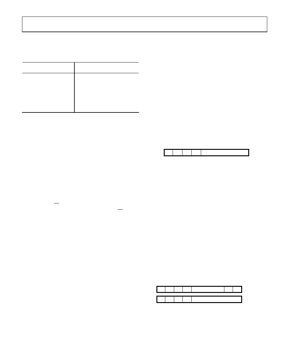
DOUT OUTPUT
The conversion result from the AD7912/AD7922 is provided on
this output as a serial data stream. The bits are clocked out on
the SCLK falling edge at the same time that the conversion is
taking place.
The serial data stream for the AD7922 consists of two leading
zeros followed by the bit that identifies the channel converted,
the bit that indicates the current mode of operation, and the
12-bit conversion result with MSB provided first.
For the AD7912, the serial data stream consists of two leading
zeros followed by the bit that identifies the channel converted,
the bit that indicates the current mode of operation, and the
10-bit conversion result with MSB provided first, followed by
two trailing zeros.
The CHN and MOD bits on DOUT indicate to the user the
current mode of operation of the ADC. If CHN = MOD,
the AD7912/AD7922 are in normal mode. Otherwise, if
CHN ≠ MOD, the AD7912/AD7922 are in daisy-chain mode.
04351-0-022
LSB
AD7912
MSB
00
0
CHN
MOD CONVERSION RESULT
AD7922
0
CHN
MOD
CONVERSION RESULT
Figure 25. AD7912/AD7922 DOUT Word
相关PDF资料 |
PDF描述 |
|---|---|
| C091 31F105 100 2 | CONN CIR FMALE 5POS R/A CABLE |
| SF6382-3SG-520 | CONN PLUG 3POS CABLE SKT |
| SP3076EEN-L | IC TXRX RS485/RS422 ESD 14NSOIC |
| D7FBAU | CONN RCPT FEMALE 7PIN BLACK/GOLD |
| MAX1113CEE+ | IC ADC 8-BIT 50KSPS 16-QSOP |
相关代理商/技术参数 |
参数描述 |
|---|---|
| AD7914 | 制造商:AD 制造商全称:Analog Devices 功能描述:4-Channel, 1 MSPS, 8-/10-/12-Bit ADCs with Sequencer in 16-Lead TSSOP |
| AD7914BRU | 制造商:Analog Devices 功能描述:ADC Single SAR 1Msps 10-bit Serial 16-Pin TSSOP 制造商:Analog Devices 功能描述:IC 10BIT ADC SMD 7914 TSSOP16 |
| AD7914BRU-REEL | 制造商:Analog Devices 功能描述:ADC Single SAR 1Msps 10-bit Serial 16-Pin TSSOP T/R 制造商:Analog Devices 功能描述:ADC SGL SAR 1MSPS 10-BIT SERL 16TSSOP - Tape and Reel 制造商:Rochester Electronics LLC 功能描述:10-BIT 4,CH 1 MSPS ADC I.C. - Tape and Reel |
| AD7914BRU-REEL7 | 制造商:Analog Devices 功能描述:ADC Single SAR 1Msps 10-bit Serial 16-Pin TSSOP T/R 制造商:Rochester Electronics LLC 功能描述:10-BIT 4,CH 1 MSPS ADC I.C. - Tape and Reel |
| AD7914BRUZ | 功能描述:IC ADC 10BIT 4CH 1MSPS 16TSSOP RoHS:是 类别:集成电路 (IC) >> 数据采集 - 模数转换器 系列:- 标准包装:1 系列:microPOWER™ 位数:8 采样率(每秒):1M 数据接口:串行,SPI? 转换器数目:1 功率耗散(最大):- 电压电源:模拟和数字 工作温度:-40°C ~ 125°C 安装类型:表面贴装 封装/外壳:24-VFQFN 裸露焊盘 供应商设备封装:24-VQFN 裸露焊盘(4x4) 包装:Digi-Reel® 输入数目和类型:8 个单端,单极 产品目录页面:892 (CN2011-ZH PDF) 其它名称:296-25851-6 |
发布紧急采购,3分钟左右您将得到回复。