- 您现在的位置:买卖IC网 > PDF目录68990 > AD8339ACPZ (ANALOG DEVICES INC) 0 MHz - 50 MHz RF/MICROWAVE I/Q DEMODULATOR PDF资料下载
参数资料
| 型号: | AD8339ACPZ |
| 厂商: | ANALOG DEVICES INC |
| 元件分类: | 调制器/解调器 |
| 英文描述: | 0 MHz - 50 MHz RF/MICROWAVE I/Q DEMODULATOR |
| 封装: | 6 X 6 MM, ROHS COMPLIANT, MO-220-VJJD-2, LFCSP-40 |
| 文件页数: | 14/36页 |
| 文件大小: | 2970K |
| 代理商: | AD8339ACPZ |
第1页第2页第3页第4页第5页第6页第7页第8页第9页第10页第11页第12页第13页当前第14页第15页第16页第17页第18页第19页第20页第21页第22页第23页第24页第25页第26页第27页第28页第29页第30页第31页第32页第33页第34页第35页第36页
AD8339
Rev. A | Page 21 of
36
Combining Phase Compensation and Analog
Beamforming
Modern ultrasound machines used for medical applications
employ an array of receivers for beamforming, with typical CW
Doppler array sizes of up to 64 receiver channels that are phase
shifted and summed together to extract coherent information.
When used in multiples, the desired signals from each of the
channels can be summed to yield a larger signal (increased by a
factor N, where N is the number of channels), and the noise is
increased by the square root of the number of channels. This
technique enhances the signal-to-noise performance of the
machine. The critical elements in a beamformer design are the
means to align the incoming signals in the time domain and the
means to sum the individual signals into a composite whole.
In traditional analog beamformers incorporating Doppler, a
V-to-I converter per channel and a crosspoint switch precede
passive delay lines used as a combined phase shifter and
summing circuit. The system operates at the carrier frequency
(RF) through the delay line, which also sums the signals from
the various channels, and then the combined signal is down-
converted by a very large dynamic range I/Q demodulator.
The resultant I and Q signals are filtered and then sampled by
two high resolution analog-to-digital converters. The sampled
signals are processed to extract the relevant Doppler information.
Alternatively, the RF signal can be processed by downconversion
on each channel individually, phase shifting the downconverted
signal, and then combining all channels. The AD8333 and the
AD8339 implement this architecture. The downconversion is done
by an I/Q demodulator on each channel, and the summed current
output is the same as in the delay line approach. The subsequent
filters after the I-to-V conversion and the ADCs are similar.
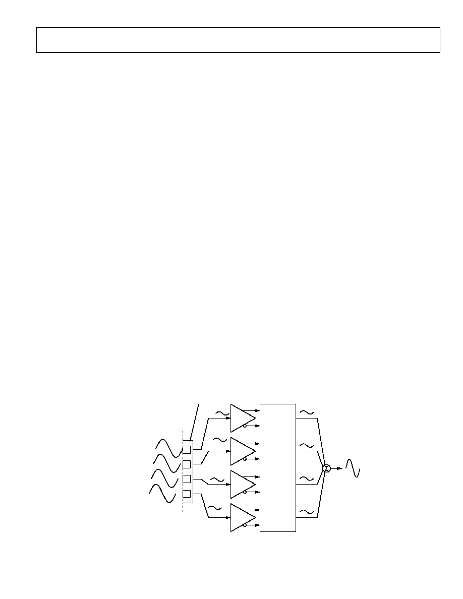
The AD8339 integrates the phase shifter, frequency conversion,
and I/Q demodulation into a single package and directly yields
the baseband signal. Figure 54 is a simplified diagram showing
the concept for all four channels. The ultrasound wave (US wave)
is received by four transducer elements, TE1 through TE4, in an
ultrasound probe and generates signals E1 through E4. In this
example, the phase at TE1 leads the phase at TE2 by 45°.
Channel Summing
Figure 55 shows a 16-channel beamformer using AD8339s,
AD8021s, and an AD797. The number of channels summed is
limited by the current drive capability of the amplifier used to
implement the active low-pass filter and current-to-voltage
converter. An AD8021 sums up to 16 AD8339 outputs.
In an ultrasound application, the instantaneous phase difference
between echo signals is influenced by the transducer-element
spacing, the wavelength (λ), the speed of sound in the media, the
angle of incidence of the probe to the target, and other factors.
In Figure 54, the signals E1 through E4 are amplified 19 dB by
the low noise amplifiers in the AD8334; for lower power portable
ultrasound applications, the AD8335 can be used instead of the
AD8334 for the lowest power per channel. For optimum signal-
to-noise performance, the output of the LNA is applied directly
to the input of the AD8339. To sum the signals E1 through E4,
E2 is shifted 45° relative to E1 by setting the phase code in
Channel 2 to 0010, E3 is shifted 90° (0100), and E4 is shifted
135° (0110). The phase aligned current signals at the output of
the AD8339 are summed in an I-to-V converter to provide the
combined output signal with a theoretical improvement in
dynamic range of 6 dB for the four channels.
06
58
7-
05
3
TRANSDUCER
ELEMENTS TE1
THROUGH TE4
CONVERT US TO
ELECTRICAL
SIGNALS
AD8334
AD8339
PHASE BIT
SETTINGS
CH 1
PHASE SET
FOR 135°
LAG
S1 THROUGH S4
ARE NOW IN
PHASE
SUMMED
OUTPUT
S1 + S2 + S3 + S4
E1
CH 2
PHASE SET
FOR 90°
LAG
19dB
LNA
E2
CH 3
PHASE SET
FOR 45°
LAG
CH 4
PHASE SET
FOR 0°
LAG
19dB
LNA
E3
19dB
LNA
E4
S1
S2
S3
S4
19dB
LNA
4 US WAVES
ARE DELAYED
45° EACH WITH
RESPECT TO
EACH OTHER
90°
45°
135°
0°
Figure 54. Simplified Example of the AD8339 Phase Shifter
相关PDF资料 |
PDF描述 |
|---|---|
| ADL5374ACPZ-WP | 3000 MHz - 4000 MHz RF/MICROWAVE QUADRAPHASE MODULATOR |
| ADL5375-05ACPZ-R7 | 400 MHz - 6000 MHz RF/MICROWAVE I/Q MODULATOR |
| AH212-S8G | 1800 MHz - 2400 MHz RF/MICROWAVE NARROW BAND MEDIUM POWER AMPLIFIER |
| AK1222 | 100 MHz - 900 MHz RF/MICROWAVE SINGLE BALANCED MIXER |
| ALM-40220-BLKG | 2010 MHz - 2025 MHz RF/MICROWAVE SGL POLE DOUBLE THROW SWITCH, 0.45 dB INSERTION LOSS |
相关代理商/技术参数 |
参数描述 |
|---|---|
| AD8339ACPZ-R7 | 功能描述:IC DEMODULATOR I/Q QUAD 40LFCSP RoHS:是 类别:RF/IF 和 RFID >> RF 解调器 系列:- 产品培训模块:Lead (SnPb) Finish for COTS Obsolescence Mitigation Program 标准包装:2,500 系列:- 功能:解调器 LO 频率:- RF 频率:70MHz ~ 300MHz P1dB:-9dBm 增益:- 噪音数据:6.36dB 电流 - 电源:41.5mA 电源电压:2.7 V 封装/外壳:28-WFQFN 裸露焊盘 供应商设备封装:28-TQFN-EP(5x5) 包装:带卷 (TR) |
| AD8339ACPZ-RL | 功能描述:IC DEMODULATOR I/Q QUAD 40LFCSP RoHS:是 类别:RF/IF 和 RFID >> RF 解调器 系列:- 产品培训模块:Lead (SnPb) Finish for COTS Obsolescence Mitigation Program 标准包装:2,500 系列:- 功能:解调器 LO 频率:- RF 频率:70MHz ~ 300MHz P1dB:-9dBm 增益:- 噪音数据:6.36dB 电流 - 电源:41.5mA 电源电压:2.7 V 封装/外壳:28-WFQFN 裸露焊盘 供应商设备封装:28-TQFN-EP(5x5) 包装:带卷 (TR) |
| AD8339-EVALZ | 功能描述:BOARD EVAL AD8339 I/Q DEMOD RoHS:是 类别:RF/IF 和 RFID >> RF 评估和开发套件,板 系列:- 标准包装:1 系列:- 类型:GPS 接收器 频率:1575MHz 适用于相关产品:- 已供物品:模块 其它名称:SER3796 |
| AD834 | 制造商:AD 制造商全称:Analog Devices 功能描述:500 MHz Four-Quadrant Multiplier |
| AD834_12 | 制造商:AD 制造商全称:Analog Devices 功能描述:500 MHz Four-Quadrant Multiplier |
发布紧急采购,3分钟左右您将得到回复。