- 您现在的位置:买卖IC网 > PDF目录373944 > AD8346-EVAL (Analog Devices, Inc.) 0.8 GHz-2.5 GHz Quadrature Modulator PDF资料下载
参数资料
| 型号: | AD8346-EVAL |
| 厂商: | Analog Devices, Inc. |
| 英文描述: | 0.8 GHz-2.5 GHz Quadrature Modulator |
| 中文描述: | 0.8千兆赫,2.5 GHz的正交调制器 |
| 文件页数: | 7/12页 |
| 文件大小: | 190K |
| 代理商: | AD8346-EVAL |
REV. 0
AD8346
–7–
CIRCUIT DESCRIPTION
OVERVIEW
The AD8346 can be divided into the following sections: Local
Oscillator (LO) Interface, Mixer, Voltage-to-Current (V-to-I)
Converter, Differential-to-Single-ended (D-to-S) Converter,
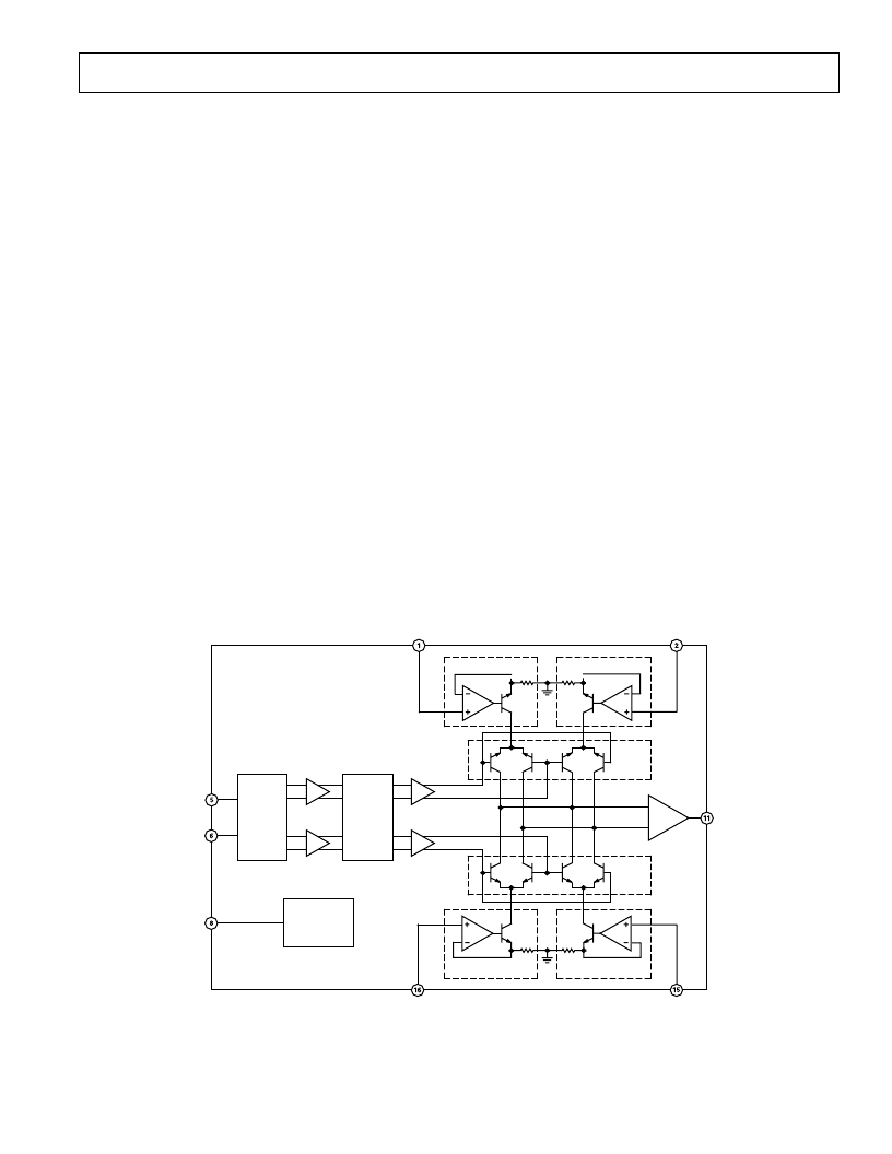
and Bias. A detailed block diagram of the part is shown in Fig-
ure 20.
The LO Interface generates two LO signals, with 90 degrees of
phase difference between them, to drive two mixers in quadra-
ture. Baseband voltage signals are converted into current form
in the V-to-I converters, feeding into two mixers. The output of
the mixers are combined to feed the D-to-S converter which
provides the 50
output interface. Bias currents to each section
are controlled by the Enable (ENBL) signal. Detailed descrip-
tion of each section follows.
LO Interface
The differential LO inputs allow the user to drive the LO differ-
entially in order to achieve maximum performance. The LO can
be driven single-endedly but the LO feedthrough performance
will be degraded, especially towards the higher end of the fre-
quency range. The LO Interface consists of interleaved stages of
polyphase network phase-splitters and buffer amplifiers. The
phase-splitter contains resistors and capacitors connected in a
circular manner to split the LO signal into I and Q paths in
precise quadrature with each other. The signal on each path
goes through a buffer amplifier to make up for the loss and high
frequency roll-off. The two signals then go through another
polyphase network to enhance the quadrature accuracy. The
broad operating frequency range of 0.8 GHz to 2.5 GHz is
achieved by staggering the RC time constants in each stage of
the phase-splitters. The outputs of the second phase-splitter are
fed into the driver amplifiers for the mixers’ LO inputs.
V-to-I Converter
Each baseband input pin is connected to an op amp driving an
emitter follower. Feedback at the emitter maintains a current
proportional to the input voltage through the transistor. This
current is fed to the two mixers in differential form.
Mixers
There are two double-balanced mixers, one for the In-Phase
Channel (I-channel) and one for the Quadrature Channel (Q-
channel). Each mixer uses the Gilbert-cell design with four
cross-connected transistors. The bases of the transistors are
driven by the LO signal of the corresponding channel. The
output currents from the two mixers are summed together in
two resistors in series with two coupled on-chip inductors. The
signal developed across the R-L loads are sent to the D-to-S stage.
Differential-to-Single-Ended Converter
The differential-to-single-ended converter consists of two emit-
ter followers driving a totem-pole output stage. Output imped-
ance is established by the emitter resistors in the output transistors.
The output of this stage is connected to the output (VOUT) pin.
Bias
A bandgap reference circuit based on the
-V
BE
principle gener-
ates the Proportional-To-Absolute-Temperature (PTAT) cur-
rents used by the different sections as references. The bandgap
voltage is also used to generate a temperature-stable current in
the V-to-I converters to produce a temperature independent
slew rate. When the bandgap reference is disabled by pulling
down the ENBL pin, all other sections are shut off accordingly.
MIXER
MIXER
V-TO-I
V-TO-I
V-TO-I
V-TO-I
D-TO-S
BIAS CELL
AD8346
LOIN
LOIP
ENBL
QBBP
QBBN
V
OUT
IBBN
IBBP
PHASE
SPLITTER
1
PHASE
SPLITTER
2
Figure 20. Detailed Block Diagram
相关PDF资料 |
PDF描述 |
|---|---|
| AD8346ARU | 0.8 GHz-2.5 GHz Quadrature Modulator |
| AD8346ARU-REEL7 | 0.8 GHz-2.5 GHz Quadrature Modulator |
| AD8347ARU-REEL | 0.8 GHz-2.7 GHz Direct Conversion Quadrature Demodulator |
| AD8347 | 0.8 GHz-2.7 GHz Direct Conversion Quadrature Demodulator |
| AD8347-EVAL | 0.8 GHz-2.7 GHz Direct Conversion Quadrature Demodulator |
相关代理商/技术参数 |
参数描述 |
|---|---|
| AD8346-EVALZ | 制造商:Analog Devices 功能描述:- Bulk |
| AD8347 | 制造商:AD 制造商全称:Analog Devices 功能描述:0.8 GHz-2.7 GHz Direct Conversion Quadrature Demodulator |
| AD8347ARU | 功能描述:IC QUADRATURE DEMOD 28-TSSOP RoHS:否 类别:RF/IF 和 RFID >> RF 解调器 系列:- 产品培训模块:Lead (SnPb) Finish for COTS Obsolescence Mitigation Program 标准包装:2,500 系列:- 功能:解调器 LO 频率:- RF 频率:70MHz ~ 300MHz P1dB:-9dBm 增益:- 噪音数据:6.36dB 电流 - 电源:41.5mA 电源电压:2.7 V 封装/外壳:28-WFQFN 裸露焊盘 供应商设备封装:28-TQFN-EP(5x5) 包装:带卷 (TR) |
发布紧急采购,3分钟左右您将得到回复。