- 您现在的位置:买卖IC网 > PDF目录373944 > AD8346-EVAL (Analog Devices, Inc.) 0.8 GHz-2.5 GHz Quadrature Modulator PDF资料下载
参数资料
| 型号: | AD8346-EVAL |
| 厂商: | Analog Devices, Inc. |
| 英文描述: | 0.8 GHz-2.5 GHz Quadrature Modulator |
| 中文描述: | 0.8千兆赫,2.5 GHz的正交调制器 |
| 文件页数: | 9/12页 |
| 文件大小: | 190K |
| 代理商: | AD8346-EVAL |
REV. 0
AD8346
–9–
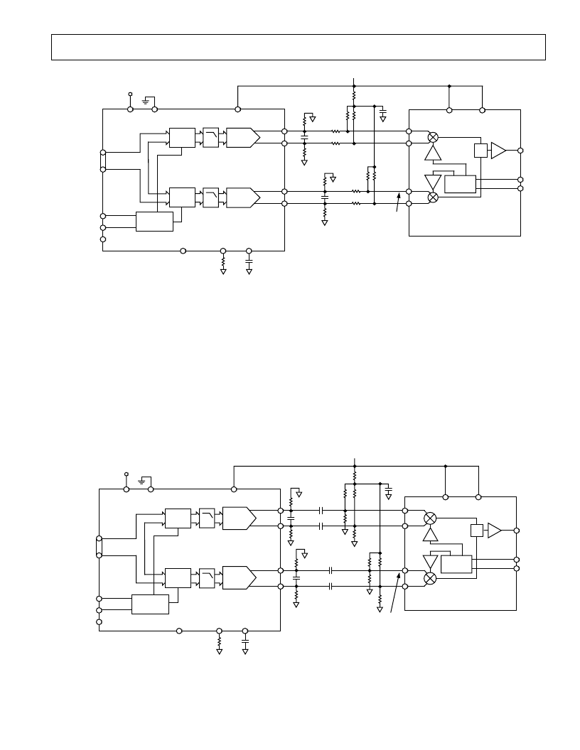
AC Coupled Interface
An ac coupled interface can also be implemented. This is shown
in Figure 24. This has the advantage that there is almost no
voltage loss due to the biasing network, allowing the AD8346
inputs to be driven by the full 2 V p-p differential signal from the
AD9761 (each of the DAC’s four outputs delivering 1 V p-p).
As in the dc coupled case, the bias levels on the I and Q inputs
should be set to as precise a level as possible, relative to each
other. This prevents the introduction of additional input offset
voltages. In the example shown, the bias level on each input is
set to approximately 1.2 V. The 2.43 k
resistors should have a
ratio tolerance of 0.1% or better.
"I"
DAC
2
3
LATCH
"I"
IOUTB
IOUTA
"Q"
DAC
2
3
LATCH
"Q"
QOUTB
QOUTA
MUX
CONTROL
SELECT
WRITE
CLOCK
AD9761
DVDD
DCOM
AVDD
0.1
m
F
R
SET
2k
V
SLEEP
FS ADJ
REFIO
DAC
DATA
INPUTS
C
FILTER
100
V
100
V
C
FILTER
100
V
100
V
500
V
500
V
500
V
500
V
0.5V p-p EACH PIN
WITH V
CM
= 1.2V
500
V
500
V
500
V
500
V
0.1
m
F
634
V
+5V
PHASE
SPLITTER
S
VOUT
IBBP
IBBN
QBBP
QBBN
AD8346
LOIP
LOIN
VPS1
VPS2
+5V
Figure 23. AD8346 Interface to AD9761 TxDAC
2
3
LATCH
"I"
IOUTB
IOUTA
2
3
LATCH
"Q"
QOUTB
QOUTA
MUX
CONTROL
SELECT
WRITE
CLOCK
AD9761
DVDD
DCOM
AVDD
0.1
m
F
R
SET
2k
V
SLEEP
FS ADJ
REFIO
DAC
DATA
INPUTS
C
FILTER
100
V
100
V
C
FILTER
100
V
100
V
0.1
m
F
1k
V
+5V
PHASE
SPLITTER
S
V
OUT
IBBP
IBBN
QBBP
QBBN
AD8346
LOIP
LOIN
VPS1
VPS2
1V p-p EACH PIN
WITH V
CM
= 1.2V
+5V
0.01
m
F
0.01
m
F
0.01
m
F
0.01
m
F
"I"
DAC
2.43k
V
2.43k
V
2.43k
V
2.43k
V
2.43k
V
2.43k
V
2.43k
V
2.43k
V
"Q"
DAC
Figure 24. AC-Coupled DAC Interface
The network shown has a high-pass corner frequency of
approximately 14.3 kHz (note that the 12 k
input imped-
ance of the AD8346 has been factored into this calcula-
tion). Increasing the resistors in the network or increasing
the coupling capacitance will reduce the corner frequency
further.
Note that the LO suppression can be manually optimized
by replacing a portion of the four “top” 2.43 k
resistors
with potentiometers. In this case, the “bottom” four resis-
tors in the biasing network would no longer need to be
precision devices.
相关PDF资料 |
PDF描述 |
|---|---|
| AD8346ARU | 0.8 GHz-2.5 GHz Quadrature Modulator |
| AD8346ARU-REEL7 | 0.8 GHz-2.5 GHz Quadrature Modulator |
| AD8347ARU-REEL | 0.8 GHz-2.7 GHz Direct Conversion Quadrature Demodulator |
| AD8347 | 0.8 GHz-2.7 GHz Direct Conversion Quadrature Demodulator |
| AD8347-EVAL | 0.8 GHz-2.7 GHz Direct Conversion Quadrature Demodulator |
相关代理商/技术参数 |
参数描述 |
|---|---|
| AD8346-EVALZ | 制造商:Analog Devices 功能描述:- Bulk |
| AD8347 | 制造商:AD 制造商全称:Analog Devices 功能描述:0.8 GHz-2.7 GHz Direct Conversion Quadrature Demodulator |
| AD8347ARU | 功能描述:IC QUADRATURE DEMOD 28-TSSOP RoHS:否 类别:RF/IF 和 RFID >> RF 解调器 系列:- 产品培训模块:Lead (SnPb) Finish for COTS Obsolescence Mitigation Program 标准包装:2,500 系列:- 功能:解调器 LO 频率:- RF 频率:70MHz ~ 300MHz P1dB:-9dBm 增益:- 噪音数据:6.36dB 电流 - 电源:41.5mA 电源电压:2.7 V 封装/外壳:28-WFQFN 裸露焊盘 供应商设备封装:28-TQFN-EP(5x5) 包装:带卷 (TR) |
发布紧急采购,3分钟左右您将得到回复。