参数资料
| 型号: | AD9765ASTZ |
| 厂商: | Analog Devices Inc |
| 文件页数: | 26/44页 |
| 文件大小: | 0K |
| 描述: | IC DAC 12BIT DUAL 125MSPS 48LQFP |
| 产品培训模块: | Data Converter Fundamentals DAC Architectures |
| 标准包装: | 1 |
| 系列: | TxDAC+® |
| 设置时间: | 35ns |
| 位数: | 12 |
| 数据接口: | 并联 |
| 转换器数目: | 2 |
| 电压电源: | 模拟和数字 |
| 功率耗散(最大): | 450mW |
| 工作温度: | -40°C ~ 85°C |
| 安装类型: | 表面贴装 |
| 封装/外壳: | 48-LQFP |
| 供应商设备封装: | 48-LQFP(7x7) |
| 包装: | 托盘 |
| 输出数目和类型: | 4 电流,单极;4 电流,双极 |
| 采样率(每秒): | 125M |
| 产品目录页面: | 785 (CN2011-ZH PDF) |
| 配用: | AD9765-EBZ-ND - BOARD EVAL FOR AD9765 |
第1页第2页第3页第4页第5页第6页第7页第8页第9页第10页第11页第12页第13页第14页第15页第16页第17页第18页第19页第20页第21页第22页第23页第24页第25页当前第26页第27页第28页第29页第30页第31页第32页第33页第34页第35页第36页第37页第38页第39页第40页第41页第42页第43页第44页
AD9763/AD9765/AD9767
Data Sheet
Rev. G | Page 32 of 44
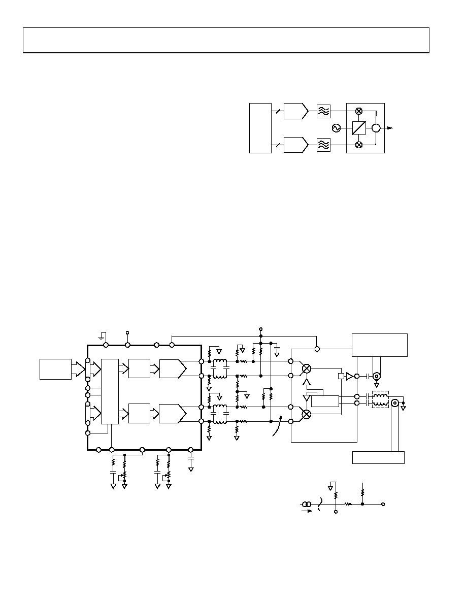
QUADRATURE AMPLITUDE MODULATION (QAM)
EXAMPLE USING THE AD9763
QAM is one of the most widely used digital modulation
schemes in digital communications systems. This modulation
technique can be found in FDM as well as spread spectrum
(that is, CDMA) based systems. A QAM signal is a carrier
frequency that is modulated in both amplitude (that is, AM
modulation) and phase (that is, PM modulation). It can be
generated by independently modulating two carriers of
identical frequency but with a 90° phase difference. This results
in an in-phase (I) carrier component and a quadrature (Q) carrier
component at a 90° phase shift with respect to the I component.
The I and Q components are then summed to provide a QAM
signal at the specified carrier frequency.
A common and traditional implementation of a QAM modulator
is shown in Figure 83. The modulation is performed in the
analog domain in which two DACs are used to generate the
baseband I and Q components. Each component is then typically
applied to a Nyquist filter before being applied to a quadrature
mixer. The matching Nyquist filters shape and limit each
component’s spectral envelope while minimizing intersymbol
interference. The DAC is typically updated at the QAM symbol
rate, or at a multiple of the QAM symbol rate if an interpolating
filter precedes the DAC. The use of an interpolating filter typically
eases the implementation and complexity of the analog filter, which
can be a significant contributor to mismatches in gain and phase
between the two baseband channels. A quadrature mixer
modulates the I and Q components with the in-phase and
quadrature carrier frequency and then sums the two outputs
to provide the QAM signal.
QUADRATURE
MODULATOR
DAC
10
DAC
CARRIER
FREQUENCY
NYQUIST
FILTERS
TO
MIXER
DSP
OR
ASIC
Σ
0°
90°
00
61
7-
08
3
Figure 83. Typical Analog QAM Architecture
In this implementation, it is much more difficult to maintain
proper gain and phase matching between the I and Q channels.
The circuit implementation shown in Figure 84 helps improve the
matching between the I and Q channels, and it shows a path for
upconversion using the AD8346 quadrature modulator. The
AD9763 provides both I and Q DACs a common reference that
improves the gain matching and stability. RCAL can be used to
compensate for any mismatch in gain between the two channels.
The mismatch can be attributed to the mismatch between RSET1
and RSET2, the effective load resistance of each channel, and/or
the voltage offset of the control amplifier in each DAC. The
differential voltage outputs of both DACs in the AD9763 are
fed into the respective differential inputs of the AD8346 via
matching networks.
AD9763/
AD9765/
AD9767
00
61
7-
08
4
IOUTA
IOUTB
IOUTA
IOUTB
DCOM1/
DCOM2
DVDD1/
DVDD2
AVDD
VPBF
BBIP
BBIN
BBQP
BBQN
LOIP
LOIN
VOUT
WRT1/IQWRT
ACOM
+
SPECTRUM ANALYZER
AD8346
CLK1/IQCLK
PO
R
T
Q
P
O
R
T
I
DI
G
IT
AL
I
NT
E
RF
ACE
I
DAC
WRT2/IQSEL
CFILTER
VDIFF = 1.82V p-p
RL
RB
RL
LA
RL
CA
RB
RA
RL
RB
RA
0 TO IOUTFS
AD8346
AVDD
AD976x
AVDD
TEKTRONIX
AWG2021
WITH
OPTION 4
I DAC
LATCH
Q DAC
LATCH
Q
DAC
NOTES
1. DAC FULL-SCALE OUTPUT CURRENT = IOUTFS.
2. RA, RB, AND RL ARE THIN FILM RESISTOR NETWORKS
WITH 0.1% MATCHING, 1% ACCURACY AVAILABLE
FROM OHMTEK ORNXXXXD SERIES OR EQUIVALENT.
VMOD
VDAC
DIFFERENTIAL
RLC FILTER
RL = 200
RA = 2500
RB = 500
RP = 200
CA = 280pF
CB = 45pF
LA = 10H
IOUTFS = 11mA
AVDD = 5.0V
VCM = 1.2V
RL
CB
0.1F
RA
CB
PHASE
SPLITTER
ROHDE & SCHWARZ
FSEA30B
OR EQUIVALENT
ROHDE & SCHWARZ
SIGNAL GENERATOR
SLEEP
FSADJ1
FSADJ2
MODE
REFIO
2k
20k
0.1F
256
22nF
2k
20k
256
22nF
Figure 84. Baseband QAM Implementation Using an AD9763 and an AD8346
相关PDF资料 |
PDF描述 |
|---|---|
| MS3120F16-8S | CONN RCPT 8POS WALL MNT W/SCKT |
| VI-J4B-MZ-F1 | CONVERTER MOD DC/DC 95V 25W |
| VI-24Z-MU-F1 | CONVERTER MOD DC/DC 2V 80W |
| MS27468T25F19PC | CONN RCPT 19POS JAM NUT W/PINS |
| VI-J1L-MZ-F4 | CONVERTER MOD DC/DC 28V 25W |
相关代理商/技术参数 |
参数描述 |
|---|---|
| AD9765ASTZ | 制造商:Analog Devices 功能描述:12BIT DAC DUAL 125MSPS 48LQFP 制造商:Analog Devices 功能描述:12BIT DAC, DUAL, 125MSPS, 48LQFP |
| AD9765ASTZKL1 | 制造商:Rochester Electronics LLC 功能描述: 制造商:Analog Devices 功能描述: |
| AD9765ASTZRL | 功能描述:IC DAC 12BIT DUAL 125MSPS 48LQFP RoHS:是 类别:集成电路 (IC) >> 数据采集 - 数模转换器 系列:TxDAC+® 产品培训模块:Data Converter Fundamentals DAC Architectures 标准包装:750 系列:- 设置时间:7µs 位数:16 数据接口:并联 转换器数目:1 电压电源:双 ± 功率耗散(最大):100mW 工作温度:0°C ~ 70°C 安装类型:表面贴装 封装/外壳:28-LCC(J 形引线) 供应商设备封装:28-PLCC(11.51x11.51) 包装:带卷 (TR) 输出数目和类型:1 电压,单极;1 电压,双极 采样率(每秒):143k |
| AD9765-EB | 制造商:Analog Devices 功能描述: |
| AD9765-EBZ | 功能描述:BOARD EVAL FOR AD9765 RoHS:是 类别:编程器,开发系统 >> 评估板 - 数模转换器 (DAC) 系列:TxDAC+® 产品培训模块:Lead (SnPb) Finish for COTS Obsolescence Mitigation Program 标准包装:1 系列:- DAC 的数量:4 位数:12 采样率(每秒):- 数据接口:串行,SPI? 设置时间:3µs DAC 型:电流/电压 工作温度:-40°C ~ 85°C 已供物品:板 已用 IC / 零件:MAX5581 |
发布紧急采购,3分钟左右您将得到回复。