- 您现在的位置:买卖IC网 > PDF目录378276 > ADAV801 (Analog Devices, Inc.) Audio Codec for Recordable DVD PDF资料下载
参数资料
| 型号: | ADAV801 |
| 厂商: | Analog Devices, Inc. |
| 元件分类: | Codec |
| 英文描述: | Audio Codec for Recordable DVD |
| 中文描述: | 音频编解码器可刻录DVD |
| 文件页数: | 21/56页 |
| 文件大小: | 1405K |
| 代理商: | ADAV801 |
第1页第2页第3页第4页第5页第6页第7页第8页第9页第10页第11页第12页第13页第14页第15页第16页第17页第18页第19页第20页当前第21页第22页第23页第24页第25页第26页第27页第28页第29页第30页第31页第32页第33页第34页第35页第36页第37页第38页第39页第40页第41页第42页第43页第44页第45页第46页第47页第48页第49页第50页第51页第52页第53页第54页第55页第56页
ADAV801
The number of inp
FIFO on the SRC is 16 plus Bit 6 to Bit 0 of the group delay
register. This feature is useful in varispeed applications to
prevent the read pointer to the FIFO from running ahead of the
write pointer. When set, Bit 7 of the group delay and mute-in
register soft-mutes the sample rate. Increasing the offset of the
write address pointer is useful for applications in which small
changes in the sample rate ratio between f
S_IN
and f
S_OUT
are
expected. The maximum decimation rate can be calculated
from the RAM word depth and the group delay as
Rev. 0 | Page 21 of 56
ut samples added to the write pointer of the
(512 16)/64 taps = 7.75
for short group delay and
(512 64)/64 taps = 7
for long group delay.
o of f
S_IN
/f
S_OUT
The digital servo loop is essentially a ramp filter that provides
the initial pointer to the address in RAM and ROM for the start
of the FIR convolution. The RAM pointer is the integer output
of the ramp filter, and the ROM is the fractional part. The
digital servo loop must provide excellent rejection of jitter on
the f
S_IN
and f
S_OUT
clocks, as well as measure the arrival of the
f
S_OUT
clock within 4.97 ps. The digital servo loop also divides
the fractional part of the ramp output by the rati
to dynamically alter the ROM coefficients when f
S_IN
> f
S_OUT
.
0
D
S
)
I
I
REG 0x00
BITS 1–0
REG 0x76
BIT 0
REG 0x76
BIT 1
REG 0x62
BITS 7–6
D
S
)
DIR
PLAYBACK
AUXILIARY IN
ADC
M
X
SRC
MCLK
SRC
OUTPUT
SRC
SRC
INPUT
P
P
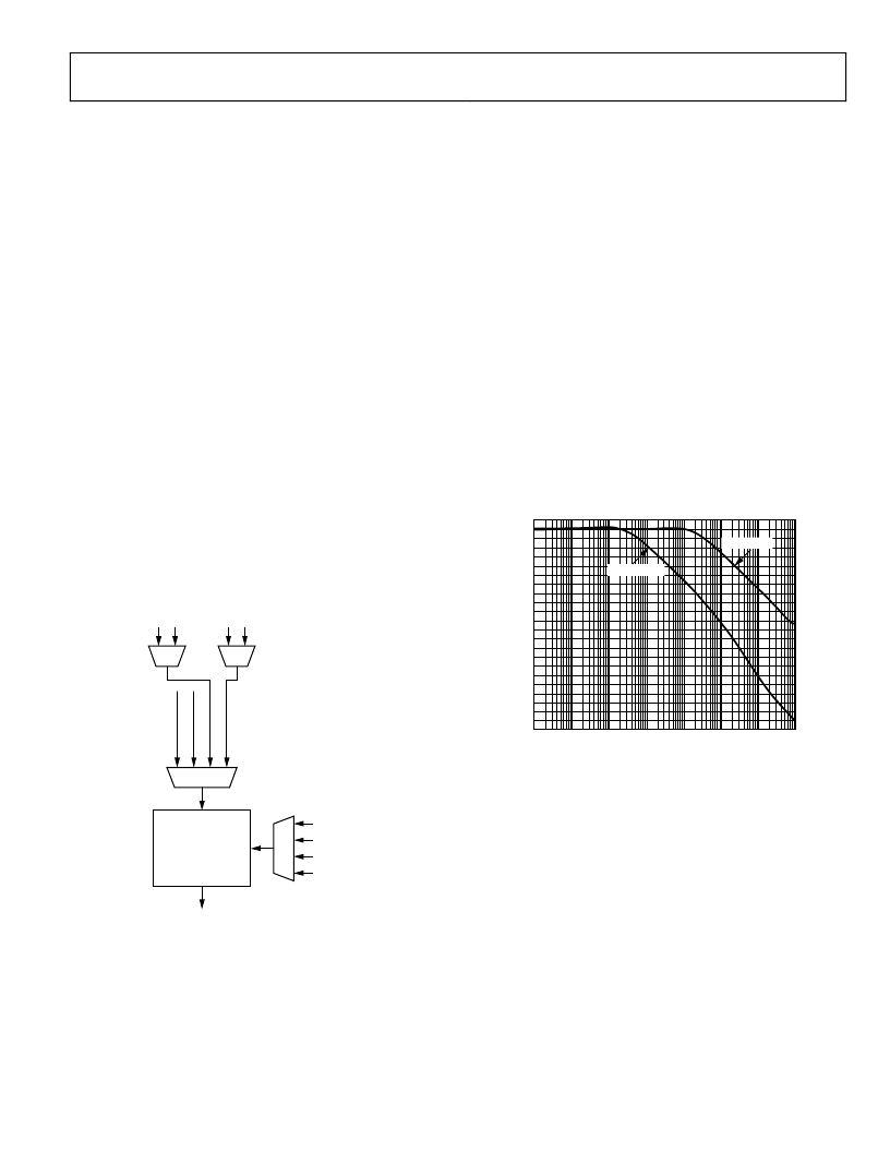
Figure 33. Clock and Datapath Control on the SCR
The digital servo loop is implemented with a multirate filter. To
ttle the digital servo loop filter more quickly upon startup or a
se
change in the sample rate, a fast mode has been
filter. When the digital servo loop starts up or the s
changed, the digital servo loop enters fast mode to adjust and
settle on the new sample rate. Upon sensing that the digital
added to the
ample rate is
easonable value, the digital
During fast mode, the MUTE_OUT bi
pres
e mu
l t
an be
m
onve
ly.
c
rted accurate
e error
he u
at clicks
tput of
ght
l audio
Bit 7 of he group delay and
ged to
n inter
when the SRC
r
he MU
ing sample rate
e
/f
S_IN
) × 2
20
ratio for
servo loop is settling down to a r
servo loop returns to normal (or slow) mode.
t in the sample rat
ser know th
data. The ou
t
slow mode. T
rupt
regist r is asserted to let t
be
ent in the digita
b
ted by asserting
unti he SRC has chan
c
set to generate a
slow
ode, indicating that t e data is be
or pops mi
the SRC can
mute registe
TE_OUT bit
changes to
The frequency responses of the digital servo loop for fast mod
and slow mode are shown in Figure 34. The FIR filter is a 64-tap
filter when f
S_OUT
≥ f
S_IN
and is (f
S_IN
/f
S_OUT
) × 64 taps when f
S_IN
>
f
S_OUT
. The FIR filter performs its convolution by loading in the
starting address of the RAM address pointer and the ROM
address pointer from the digital servo loop at the start of the
f
S_OUT
period. The FIR filter then steps through the RAM by
decrementing its address by 1 for each tap, and the ROM
pointer increments its address by the (f
S_OUT
f
S_IN
> f
S_OUT
or 2
20
for f
S_OUT
≥ f
S_IN
. Once the ROM address rolls
over, the convolution is completed.
0
FREQUENCY (Hz)
M
0
–20
–40
–60
–80
–100
–120
–140
–160
–180
–200
0.01
0.1
1
10
100
1k
10k
100k
SLOW MODE
FAST MODE
–220
Figure 34. Frequency Response of the Digital Servo Loop. f
S_IN
is the X-Axis,
f
S_OUT
= 192 KHz, Master Clock is 30 MHz
The convolution is performed for both the left and right
channels, and the multiply accumulate circuit used for the
convolution is shared between the channels. The f
S_IN
/f
S_OUT
sample rate ratio circuit is used to dynam cally alter the
in the ROM when f
S_IN
> f
S_OUT
. The ratio is
calculated by comparing the output of an f
S_OUT
counter to the
output of an f
S_IN
counter. If f
S_OUT
> f
S_IN
, the ratio is held at one.
UT
, the sample rate ratio is updated, if it is different
by more than two f
S_OUT
periods from the previous f
S_OUT
to f
S_IN
comparison. This is done to provide some hysteresis to prevent
the filter length from oscillating and causing distortion.
coefficients
If f
S_IN
> f
S_O
相关PDF资料 |
PDF描述 |
|---|---|
| ADAV801ASTZ | Audio Codec for Recordable DVD |
| ADAV801ASTZ-REEL | Audio Codec for Recordable DVD |
| ADC0800PCD | ADC0800 8-Bit A/D Converter |
| ADC0800PD | ADC0800 8-Bit A/D Converter |
| ADC0800 | ECONOLINE: REC3-S_DRW(Z)/H* - 3W DIP Package- 1kVDC Isolation- Wide Input 2:1 & 4:1- Regulated Output- 100% Burned In- UL94V-0 Package Material- Continuous Short Circiut Protection- Efficiency to 80% |
相关代理商/技术参数 |
参数描述 |
|---|---|
| ADAV801AST | 制造商:Analog Devices 功能描述:AUDIO CODEC FOR RECORDABLE DVD - Bulk |
| ADAV801ASTZ | 功能描述:IC CODEC AUDIO R-DVD 3.3V 64LQFP RoHS:是 类别:集成电路 (IC) >> 接口 - 编解码器 系列:- 标准包装:2,500 系列:- 类型:立体声音频 数据接口:串行 分辨率(位):18 b ADC / DAC 数量:2 / 2 三角积分调变:是 S/N 比,标准 ADC / DAC (db):81.5 / 88 动态范围,标准 ADC / DAC (db):82 / 87.5 电压 - 电源,模拟:2.6 V ~ 3.3 V 电压 - 电源,数字:1.7 V ~ 3.3 V 工作温度:-40°C ~ 85°C 安装类型:表面贴装 封装/外壳:48-WFQFN 裸露焊盘 供应商设备封装:48-TQFN-EP(7x7) 包装:带卷 (TR) |
| ADAV801ASTZ-REEL | 功能描述:IC CODEC AUDIO R-DVD 3.3V 64LQFP RoHS:是 类别:集成电路 (IC) >> 接口 - 编解码器 系列:- 标准包装:2,500 系列:- 类型:立体声音频 数据接口:串行 分辨率(位):18 b ADC / DAC 数量:2 / 2 三角积分调变:是 S/N 比,标准 ADC / DAC (db):81.5 / 88 动态范围,标准 ADC / DAC (db):82 / 87.5 电压 - 电源,模拟:2.6 V ~ 3.3 V 电压 - 电源,数字:1.7 V ~ 3.3 V 工作温度:-40°C ~ 85°C 安装类型:表面贴装 封装/外壳:48-WFQFN 裸露焊盘 供应商设备封装:48-TQFN-EP(7x7) 包装:带卷 (TR) |
| ADAV802AST | 制造商:Analog Devices 功能描述:AUDIO CODEC FOR RECORDABLE DVD - Bulk |
| ADAV802ASTZ | 制造商:Analog Devices 功能描述: |
发布紧急采购,3分钟左右您将得到回复。