- 您现在的位置:买卖IC网 > PDF目录378276 > ADAV801ASTZ (ANALOG DEVICES INC) Audio Codec for Recordable DVD PDF资料下载
参数资料
| 型号: | ADAV801ASTZ |
| 厂商: | ANALOG DEVICES INC |
| 元件分类: | 消费家电 |
| 英文描述: | Audio Codec for Recordable DVD |
| 中文描述: | SPECIALTY CONSUMER CIRCUIT, PDSO64 |
| 封装: | ROHS COMPLIANT, MS-026BCD, LQFP-64 |
| 文件页数: | 26/56页 |
| 文件大小: | 1405K |
| 代理商: | ADAV801ASTZ |
第1页第2页第3页第4页第5页第6页第7页第8页第9页第10页第11页第12页第13页第14页第15页第16页第17页第18页第19页第20页第21页第22页第23页第24页第25页当前第26页第27页第28页第29页第30页第31页第32页第33页第34页第35页第36页第37页第38页第39页第40页第41页第42页第43页第44页第45页第46页第47页第48页第49页第50页第51页第52页第53页第54页第55页第56页
ADAV801
Table 11. RxBCONF3 Functionality
RxBCONF0
Receiver Us
0
384 bits with Preamble Z as the start of the block.
1
768 bits with Preamble Z as the start of the block.
Rev. 0 | Page 26 of 56
er Bit Buffer Size
The updating of the user bit buffer is controlled by Bits
RxBCONF2–1 and Bit 7 to Bit 4 of the channel status register, as
shown in Table 12 and Table 13.
Table 12. RxBCONF2–1 Functionality
RxBCONF
Bit 2
Bit 1
Receiver User Bit Buffer Configuration
0
0
User bits are ignored.
0
1
Update second buffer when first buffer is full.
1
0
Format according to Byte 1, Bit 4 to Bit 7, if
PRO bit is set. Format according to
IEC60958-3, if PRO bit is clear.
Table 13. Automatic User Bit Configuration
Bits
7
6
5
4
Configuration
0
0
0
0
User bits are ignored.
0
1
0
0
AES-18 format: the user bit buffer is treated in
the same way as when RxBCONF2–1 = 0b01.
1
0
0
0
User bit buffer is updated in the same way as
when RxBCONF2–1 = 0b01 and RxBCONF0 =
0b00.
1
1
0
0
User-defined format: the user bit buffer is
treated in the same way as when RxBCONF2–1
= 0b01.
Automatic Receiver User Bit Buffer
When the user bit buffer has been filled, the RxUBINT
interrupt bit in the interrupt status register is set, provided that
the RxUBINT mask bit is set, to indicate that the buffer has new
information and can
be read.
se when the user data is formatted according
For the special ca
to the IEC60958-3 standard into messages made of information
units, called IUs, the zeros stuffed between each IU and each
message are removed and only the IUs are stored. Once the end
of the message is sensed by more that eight zeros between IUs,
the user bit buffer is updated with the complete messag
first buffer begins looking for the start of the next message.
e and the
ed in
,
e
nel status buffer occupies
ts
ing
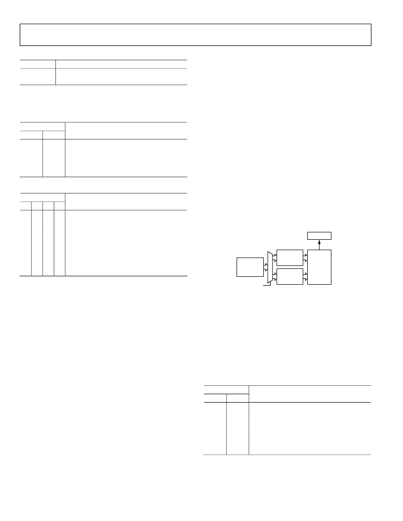
r into the SPDIF transmitter buffer until
finished loading the buffers. This feature is typically
used, if the Channel A data and Channel B data are different.
Setting the bit prevents the data from being copied. Clearing th
bit allows the data to be copied and then transmitted. Figure 48
shows how the buffers are organized.
e
Each IU is stored as a byte consisting of 1, Q, R, S, T, U, V, and W
bits (see the IEC60958-3 specification for more information).
When 96 IUs are received, the Q subcode of the IUs is stor
the Q subcode buffer, consisting of 10 bytes. The Q subcode is
the Q bits taken from each of the 96 IUs. The first 10 bytes
(80 bits) of the Q subcode contain information sent by CD, MD
and DAT systems. The last 16 bits of the Q subcode are used to
perform a CRC check of the Q subcode. If an error occurs in
the CRC check of the Q subcode, the QCRCERROR bit is set.
This is a sticky bit that remains high until the register is read.
Transmitter Operation
The SPDIF transmitter has a similar buffer structure to th
receive section. The transmitter chan
24 bytes of the register map. This buffer is long enough to store
the 192 bits required for one channel of channel status informa-
tion. Setting the TxCSSWITCH bit determines if the data
loaded to the transmitter channel status buffer is intended for
Channel A or Channel B. In most cases, the channel status bi
for Channel A and Channel B are the same, in which case
setting the Tx_A/B_Same bit reads the data from the trans-
mitter channel status buffer and transmits it on both channels.
Because the channel status information is rarely changed dur
transmission, the information contained in the buffer is
transmitted repeatedly. The Disable_Tx_Copy bit can be used to
prevent the channel status bits from being copied from the
transmitter CS buffe
the user has
0
TxCSSWITCH
TRANSMIT
CS BUFFER
(0x38–0x4F)
CHANNEL
STATUS A
(24 × 8 BITS)
CHANNEL
STATUS B
(24 × 8 BITS)
DITOUT
SPDIF
TRANSMIT
BUFFER
Figure 48. Transmitter Channel Status Buffer
As with the receiver section, the transmitted user bits are als
double-buffered. This is required, be
status bits, the user bits do not necessarily repeat themselves.
The user bits can be buffered in various configurations, as listed
in Table 14. Transmission of the user bits is determined by th
state of the BCONF3 bit. If the bit is 0, the user bits begin
transmitting right away with
this bit is 1, the user bits do not start transm
Z preamble occurs when the TxBCONF2–1
Ta
ansmitter User Bit Buffer Config
Tx
Bit 2
Bit 1
Transmitter User Bit Buffer Configuration
0
0
Zeros are transmitted for the user bits.
0
1
Host writes user bits to the buffer until it is full.
1
0
Writes the user bits to the buffer in IUs
specified by IEC60958-3 and transmits them
according to the standard.
1
1
First 10 bytes of the user-bit buffer are
configured to store a Q subcode.
o
cause, unlike the channel
e
out alignment to the Z preamble. If
itting until a
bits are 01.
ble 14. Tr
BCONF2-1
urations
相关PDF资料 |
PDF描述 |
|---|---|
| ADAV801ASTZ-REEL | Audio Codec for Recordable DVD |
| ADC0800PCD | ADC0800 8-Bit A/D Converter |
| ADC0800PD | ADC0800 8-Bit A/D Converter |
| ADC0800 | ECONOLINE: REC3-S_DRW(Z)/H* - 3W DIP Package- 1kVDC Isolation- Wide Input 2:1 & 4:1- Regulated Output- 100% Burned In- UL94V-0 Package Material- Continuous Short Circiut Protection- Efficiency to 80% |
| ADC08031 | 8-Bit High-Speed Serial I/O A/D Converters with Multiplexer Options, <BR> Voltage Reference, and Track/Hold Function |
相关代理商/技术参数 |
参数描述 |
|---|---|
| ADAV801ASTZ-REEL | 功能描述:IC CODEC AUDIO R-DVD 3.3V 64LQFP RoHS:是 类别:集成电路 (IC) >> 接口 - 编解码器 系列:- 标准包装:2,500 系列:- 类型:立体声音频 数据接口:串行 分辨率(位):18 b ADC / DAC 数量:2 / 2 三角积分调变:是 S/N 比,标准 ADC / DAC (db):81.5 / 88 动态范围,标准 ADC / DAC (db):82 / 87.5 电压 - 电源,模拟:2.6 V ~ 3.3 V 电压 - 电源,数字:1.7 V ~ 3.3 V 工作温度:-40°C ~ 85°C 安装类型:表面贴装 封装/外壳:48-WFQFN 裸露焊盘 供应商设备封装:48-TQFN-EP(7x7) 包装:带卷 (TR) |
| ADAV802AST | 制造商:Analog Devices 功能描述:AUDIO CODEC FOR RECORDABLE DVD - Bulk |
| ADAV802ASTZ | 制造商:Analog Devices 功能描述: |
| ADAV803 | 制造商:AD 制造商全称:Analog Devices 功能描述:Audio Codec for Recordable DVD |
| ADAV803AST | 制造商:Analog Devices 功能描述:AUDIO CODEC FOR RECORDABLE DVD - Bulk |
发布紧急采购,3分钟左右您将得到回复。