- 您现在的位置:买卖IC网 > PDF目录10938 > ADAV803ASTZ-REEL (Analog Devices Inc)IC CODEC AUDIO R-DVD 3.3V 64LQFP PDF资料下载
参数资料
| 型号: | ADAV803ASTZ-REEL |
| 厂商: | Analog Devices Inc |
| 文件页数: | 14/60页 |
| 文件大小: | 0K |
| 描述: | IC CODEC AUDIO R-DVD 3.3V 64LQFP |
| 标准包装: | 1,500 |
| 类型: | 音频编解码器 |
| 数据接口: | 串行 |
| 分辨率(位): | 24 b |
| ADC / DAC 数量: | 2 / 2 |
| 三角积分调变: | 无 |
| 动态范围,标准 ADC / DAC (db): | 102 / 101 |
| 电压 - 电源,模拟: | 3 V ~ 3.6 V |
| 电压 - 电源,数字: | 3 V ~ 3.6 V |
| 工作温度: | -40°C ~ 85°C |
| 安装类型: | 表面贴装 |
| 封装/外壳: | 64-LQFP |
| 供应商设备封装: | 64-LQFP(10x10) |
| 包装: | 带卷 (TR) |
| 配用: | EVAL-ADAV803EBZ-ND - BOARD EVALUATION FOR ADAV803 |
第1页第2页第3页第4页第5页第6页第7页第8页第9页第10页第11页第12页第13页当前第14页第15页第16页第17页第18页第19页第20页第21页第22页第23页第24页第25页第26页第27页第28页第29页第30页第31页第32页第33页第34页第35页第36页第37页第38页第39页第40页第41页第42页第43页第44页第45页第46页第47页第48页第49页第50页第51页第52页第53页第54页第55页第56页第57页第58页第59页第60页
ADAV803
Rev. A | Page 21 of 60
write address pointer is useful for applications in which small
changes in the sample rate ratio between fS_IN and fS_OUT are
expected. The maximum decimation rate can be calculated
from the RAM word depth and the group delay as
(512 16)/64 taps = 7.75
for short group delay and
(512 64)/64 taps = 7
for long group delay.
The digital servo loop is essentially a ramp filter that provides
the initial pointer to the address in RAM and ROM for the start
of the FIR convolution. The RAM pointer is the integer output
of the ramp filter, and the ROM is the fractional part. The
digital servo loop must provide excellent rejection of jitter on
the fS_IN and fS_OUT clocks, as well as measure the arrival of the
fS_OUT clock within 4.97 ps. The digital servo loop also divides
the fractional part of the ramp output by the ratio of fS_IN/fS_OUT
to dynamically alter the ROM coefficients when fS_IN > fS_OUT.
04
75
6-
0
33
DI
R
P
L
(256
×
f S
)
IC
LK
2
IC
LK
1
REG 0x00
BITS[1:0]
REG 0x77
BIT[4:3]
REG 0x76
BIT[1:0]
REG 0x62
BITS[7:6]
DI
R
P
L
(512
×
f S
)
DIR
PLAYBACK
AUXILIARY IN
ADC
MC
L
K
I
XI
N
SRC
MCLK
SRC
OUTPUT
SRC
INPUT
PL
L
IN
T
2
PL
L
IN
T
1
MC
L
K
I
XI
N
PL
L
IN
T
2
PL
L
IN
T
1
Figure 33. Clock and Datapath Control on the SRC
The digital servo loop is implemented with a multirate filter. To
settle the digital servo loop filter more quickly upon startup or a
change in the sample rate, a fast mode has been added to the
filter. When the digital servo loop starts up or the sample rate is
changed, the digital servo loop enters fast mode to adjust and
settle on the new sample rate. Upon sensing that the digital
servo loop is settling down to a reasonable value, the digital
servo loop returns to normal (or slow) mode.
During fast mode, the MUTE_IND bit in the s Sample Rate
Converter Error register is asserted to let the user know that
clicks or pops might be present in the digital audio data. The
output of the SRC can be muted by asserting Bit 7 of the Group
Delay and Mute register until the SRC has changed to slow
mode. The MUTE_IND bit can be set to generate an interrupt
when the SRC changes to slow mode, indicating that the data is
being sample rate converted accurately.
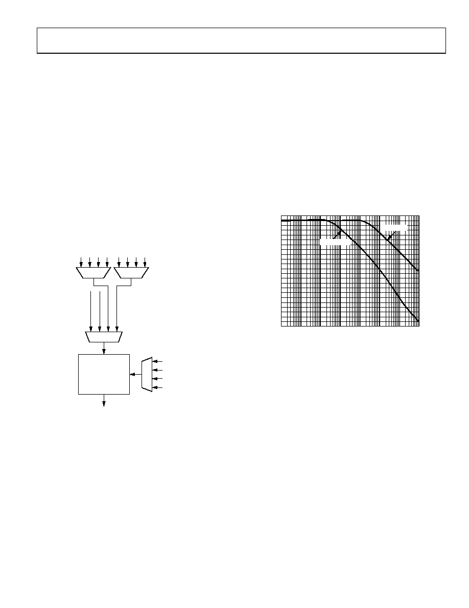
The frequency responses of the digital servo loop for fast mode
and slow mode are shown in Figure 34. The FIR filter is a 64-tap
filter when fS_OUT ≥ fS_IN and is (fS_IN/fS_OUT) × 64 taps when fS_IN >
fS_OUT. The FIR filter performs its convolution by loading in the
starting address of the RAM address pointer and the ROM
address pointer from the digital servo loop at the start of the
fS_OUT period. The FIR filter then steps through the RAM by
decrementing its address by 1 for each tap, and the ROM
pointer increments its address by the (fS_OUT/fS_IN) × 220 ratio for
fS_IN > fS_OUT or 220 for fS_OUT ≥ fS_IN. Once the ROM address rolls
over, the convolution is completed.
04
75
6
-03
4
FREQUENCY (Hz)
M
AG
NI
T
UDE
(
d
B
)
0
–20
–40
–60
–80
–100
–120
–140
–160
–180
–200
0.01
0.1
1
10
100
1k
10k
100k
SLOW MODE
FAST MODE
–220
Figure 34. Frequency Response of the Digital Servo Loop;
fS_IN is the X-Axis, fS_OUT = 192 kHz, Master Clock is 30 MHz
The convolution is performed for both the left and right
channels, and the multiply accumulate circuit used for the
convolution is shared between the channels. The fS_IN/fS_OUT
sample rate ratio circuit is used to dynamically alter the
coefficients in the ROM when fS_IN > fS_OUT. The ratio is
calculated by comparing the output of an fS_OUT counter to the
output of an fS_IN counter. If fS_OUT > fS_IN, the ratio is held at one.
If fS_IN > fS_OUT, the sample rate ratio is updated, if it is different
by more than two fS_OUT periods from the previous fS_OUT to fS_IN
comparison. This is done to provide some hysteresis to prevent
the filter length from oscillating and causing distortion.
Figure 33 shows the detail of the SRC section. The SRC master
clock is expected to be equal to 256 times the output sample
rate. This master clock can be provided by four different clock
sources. The selection is set by the SRC and Clock Control
register (Address 0x00), and the selected clock source can be
divided using the same register.
相关PDF资料 |
PDF描述 |
|---|---|
| AD1939YSTZRL | IC CODEC 24BIT ADC/DAC 64-LQFP |
| AD1937WBSTZ-RL | IC CODEC 4/ADC DIFF OUT 64-LQFP |
| AD1938WBSTZ-RL | IC CODEC 24BIT 4ADC/8DAC 48LQFP |
| AD1938YSTZRL | IC CODEC 24BIT 4ADC/8DAC 48LQFP |
| MCF5213LCVM80 | IC MCU 256K FLASH 80MHZ 81MAPBGA |
相关代理商/技术参数 |
参数描述 |
|---|---|
| ADAV804AST | 制造商:Analog Devices 功能描述:AUDIO CODEC FOR RECORDABLE DVD - Bulk |
| ADAV804ASTZ | 制造商:Analog Devices 功能描述: |
| ADB.1X40 | 制造商:FACOM 功能描述:SCREWDRIVER STUB POZI NO.1 制造商:FACOM 功能描述:SCREWDRIVER, STUB, POZI NO.1 制造商:FACOM 功能描述:SCREWDRIVER, STUB, POZI NO.1; Overall Length:90mm; Blade Length:40mm; SVHC:No SVHC (19-Dec-2012); Range:PZ1; Screwdriver Type:Pozi; Tip / Nozzle Size:PZ1; Tip / Nozzle Style:Pozidriv ;RoHS Compliant: NA |
| ADB0039 | 制造商:AVOCENT 功能描述:Cyclades - Crossover adapter - RJ-45 (M) - RJ-45 (F) |
| ADB-1 | 制造商:IDEC CORPORATION 功能描述:LACHING BEAM ATTACH |
发布紧急采购,3分钟左右您将得到回复。