- 您现在的位置:买卖IC网 > PDF目录1899 > ADP5588ACPZ-R7 (Analog Devices Inc)IC KEYPAD SCANNER GPIO PORT EXP PDF资料下载
参数资料
| 型号: | ADP5588ACPZ-R7 |
| 厂商: | Analog Devices Inc |
| 文件页数: | 27/28页 |
| 文件大小: | 0K |
| 描述: | IC KEYPAD SCANNER GPIO PORT EXP |
| 标准包装: | 1 |
| 应用: | 键盘和警报系统 |
| 接口: | I²C |
| 电源电压: | 1.8 V ~ 3 V |
| 封装/外壳: | 24-VFQFN 裸露焊盘,CSP |
| 供应商设备封装: | 24-LFCSP-VQ(4x4) |
| 包装: | 标准包装 |
| 安装类型: | 表面贴装 |
| 产品目录页面: | 799 (CN2011-ZH PDF) |
| 其它名称: | ADP5588ACPZ-R7DKR |
第1页第2页第3页第4页第5页第6页第7页第8页第9页第10页第11页第12页第13页第14页第15页第16页第17页第18页第19页第20页第21页第22页第23页第24页第25页第26页当前第27页第28页
ADP5588
Data Sheet
Rev. C | Page 8 of 28
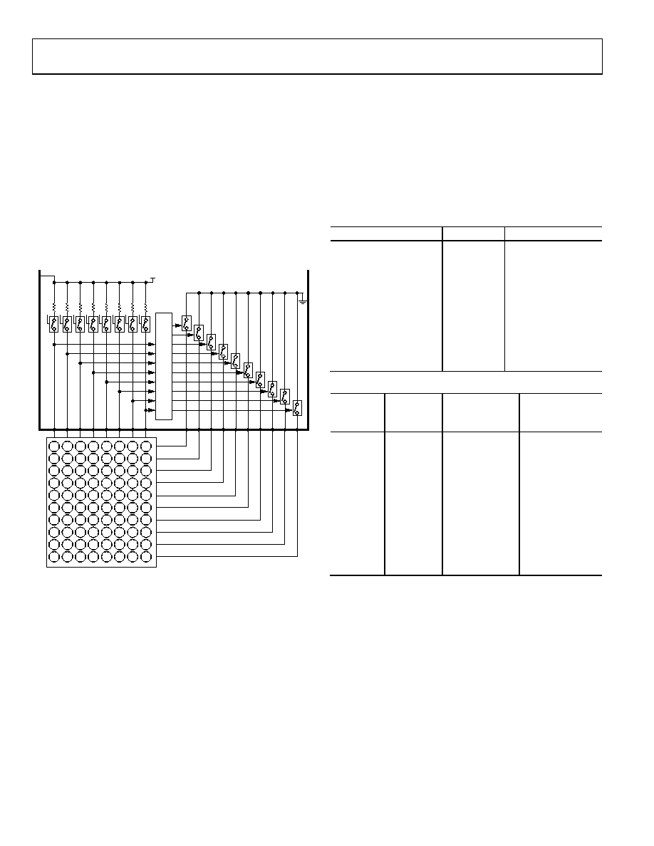
To prevent glitches or narrow press times registering as valid
key presses, the key scanner requires the key to be pressed for
two scan cycles. The key scanner has a sampling period of 25 ms,
so the key must be pressed and held for at least 25 ms to register
as pressed. If the key is continuously pressed, the key scanner
continues to sample every 25 ms. If a key that was pressed is
released for 25 ms or greater, the state machine sets the appro-
priate keys in the key event status register with the key pressed
bits cleared in the order detected. Because the release of a key is
not necessarily in sync with the key scan sampling period, it may
take between 25 ms and 50 ms for a key to register as released.
After the key is registered as released, the key scanner goes back
to idle mode. Figure 5 shows the row and column pins
connected to a typical 10 × 8, 80-switch keypad matrix.
KE
Y
P
AD
S
CAN
AND
DE
CO
DE
D0_P
UL
L
J7
I7
H7
G7
F7
E7
D7
C7
B7
A7
J6
I6
H6
G6
F6
E6
D6
C6
B6
A6
J5
I5
H5
G5
F5
E5
D5
C5
B5
A5
J4
I4
H4
G4
F4
E4
D4
C4
B4
A4
J3
I3
H3
G3
F3
E3
D3
C3
B3
A3
J2
I2
H2
G2
F2
E2
D2
C2
B2
A2
J1
I1
H1
G1
F1
E1
D1
C1
B1
A1
J0
I0
H0
G0
F0
E0
D0
C0
B0
A0
R7 R6 R5 R4 R3 R2 R1 R0
C0 C1 C2 C3 C4 C5 C6 C7
C9
C8
10 × 8 KEYPAD MATRIX
VCC
D1_P
UL
L
D2_P
UL
L
D3_P
UL
L
D4_P
UL
L
D5_P
UL
L
D6_P
UL
L
D7_P
UL
L
07673-
010
Figure 5. Keypad Decode Configuration
Key Event Tracking
The 10-key event registers are set to act as a FIFO, meaning that
reading any of the 10-key event registers yields the key events in
the order they were pressed and released.
Tracking of key events is done with the help of the key event
counter (the KEC field in Register 0x03) and the FIFO/key
event registers (Register 0x04 through Register 0x0D). The KEC
count increases as keys are pressed and released; up to 10 events
can be logged in the counter. The FIFO/key event registers, on
the other hand, display the key events and their status (pressed
or released) as they are read out of the FIFO. The FIFO registers
are made of eight bits, with the MSB dedicated as the status bit
(1 indicates a press and 0 indicates a release); the remaining
seven bits are used to display binary representation of the keys
that are pressed or released.
The first read of any of the FIFO registers displays the first
event that happened and its status. Subsequent reads of the
same register replace the register data with the next event that
happens. If tracking of all the events is important, it is best to
used a single register per event. After all the events in the FIFO
are read, reading of any of the event registers yields a zero value.
Table 11 and Table 12 show the event sequences as they are
logged in and read from the FIFO. The 10 FIFO registers are
labeled A through J, and keys are labeled A0 through J7.
Table 11. Example of Event Sequence
Key Pressed/Released
Status
Key Event Counter
A0
Pressed
1
B1
Pressed
2
A0
Released
3
C2
Pressed
4
B1
Released
5
D3
Pressed
6
C2
Released
7
E4
Pressed
8
E4
Released
9
D3
Released
10
Table 12. Interpretation of FIFO Event Reading
Key Event
Counter
Key Event
Register
Read
Key Event Reg-
ister Content
(Binary)1
Key Event
Register
Interpretation
10
N/A
9
D
1 0000001
Key A0 pressed
8
E
1 0001100
Key B1 pressed
7
C
0 0000001
Key A0 released
6
F
1 0010111
Key C2 pressed
5
G
0 0001100
Key B1 released
4
A
1 0100010
Key D3 pressed
3
B
0 0010111
Key C2 released
2
H
1 0101101
Key E4 pressed
1
J
0 0101101
Key E4 released
0
I
0 0100010
Key D3 released
1
The first number indicates a key press or key release in Bit 7 of the key event
register: 1 = key press; 0 = key release.
Key Event Overflow
The ADP5588 is equipped with an overflow feature to handle
key events beyond the FIFO capacity. When all events are filled, any
additional events set the OVR_FLOW_INT bit in Register 0x02;
if the OVR_FLOW_IEN bit in Register 0x01 is set, the host
processor is also interrupted when overflow occurs. When the
FIFO is not full, new events are added as the last events.
The OVR_FLOW_M bit in Register 0x01 sets the mode of
operation during overflows. Clearing the OVR_FLOW_M bit
causes new incoming events to be discarded, and setting this bit
rolls over and overwrites old data with new data starting at the
first event.
相关PDF资料 |
PDF描述 |
|---|---|
| ADP5589ACPZ-00-R7 | IC KEY DECODER 19I/O EXP 24LFCSP |
| ADSP-2104BPZ-80 | IC DSP CONTROLLER 16BIT 68PLCC |
| ADSP-21060LCW-160 | IC DSP CONTROLLER 32BIT 240CQFP |
| ADSP-21061KS-200 | IC DSP CONTROLLER 32BIT 240MQFP |
| ADSP-21065LCCA-240 | IC DSP CTLR 32BIT 196CSPBGA |
相关代理商/技术参数 |
参数描述 |
|---|---|
| ADP5588ACPZ-R7B2 | 功能描述:Keypads and Alarm Systems Interface 24-LFCSP-WQ (4x4) 制造商:analog devices inc. 系列:- 包装:带卷(TR) 零件状态:上次购买时间 应用:键盘和警报系统 接口:I2C 电压 - 电源:1.8 V ~ 3 V 封装/外壳:24-WFQFN 裸露焊盘,CSP 供应商器件封装:24-LFCSP-WQ(4x4) 安装类型:表面贴装 标准包装:1 |
| ADP5588-EVALZ | 功能描述:BOARD EVAL ADP5588 KEYPAD/GPIO RoHS:是 类别:编程器,开发系统 >> 评估演示板和套件 系列:- 标准包装:1 系列:- 主要目的:电信,线路接口单元(LIU) 嵌入式:- 已用 IC / 零件:IDT82V2081 主要属性:T1/J1/E1 LIU 次要属性:- 已供物品:板,电源,线缆,CD 其它名称:82EBV2081 |
| ADP5588XCPZ-R7 | 功能描述:Keypads and Alarm Systems Interface 制造商:analog devices inc. 系列:- 包装:- 零件状态:上次购买时间 应用:键盘和警报系统 接口:I2C 电压 - 电源:1.8 V ~ 3 V 封装/外壳:- 供应商器件封装:- 安装类型:- 标准包装:1 |
| ADP5588XCPZ-X2-R7 | 功能描述:Keypads and Alarm Systems Interface 制造商:analog devices inc. 系列:- 包装:- 零件状态:上次购买时间 应用:键盘和警报系统 接口:I2C 电压 - 电源:1.8 V ~ 3 V 封装/外壳:- 供应商器件封装:- 安装类型:- 标准包装:1 |
| ADP5589ACBZ-00-R7 | 功能描述:IC PORT EXPANDER 19I/O 25WLSCP RoHS:是 类别:集成电路 (IC) >> 接口 - 专用 系列:* 特色产品:NXP - I2C Interface 标准包装:1 系列:- 应用:2 通道 I²C 多路复用器 接口:I²C,SM 总线 电源电压:2.3 V ~ 5.5 V 封装/外壳:16-TSSOP(0.173",4.40mm 宽) 供应商设备封装:16-TSSOP 包装:剪切带 (CT) 安装类型:表面贴装 产品目录页面:825 (CN2011-ZH PDF) 其它名称:568-1854-1 |
发布紧急采购,3分钟左右您将得到回复。