- 您现在的位置:买卖IC网 > PDF目录20503 > APEK4403GEU-01-T-DK (Allegro Microsystems Inc)BOARD EVAL FOR A4403 PDF资料下载
参数资料
| 型号: | APEK4403GEU-01-T-DK |
| 厂商: | Allegro Microsystems Inc |
| 文件页数: | 10/16页 |
| 文件大小: | 0K |
| 描述: | BOARD EVAL FOR A4403 |
| 标准包装: | 1 |
| 主要目的: | DC/DC,步降 |
| 输出及类型: | 1,非隔离 |
| 输入电压: | 9 V ~ 46 V |
| 稳压器拓扑结构: | 降压 |
| 板类型: | 完全填充 |
| 已供物品: | 板,CD |
| 已用 IC / 零件: | A4403 |
| 相关产品: | 620-1273-2-ND - IC REG BUCK ADJ 3A 16QFN |
| 其它名称: | 620-1387 |
�� �
�
�A4403�
�Valley� Current� Mode� Control� Buck� Converter�
�The� amount� of� capacitance� required� for� a� given� ripple� voltage� can�
�be� found:�
�The� sense� resistor� value� is� selected� depending� on� the� maximum�
�output� load� current.� The� typical� sense� voltage� that� causes� a� cur-�
�C� IN� =�
�I� rms� � T� on�
�V� RIPPLE�
�.�
�(15)�
�rent� limit� is� 180� mV.� So,� for� example,� a� 50� m� Ω� value� would� be�
�appropriate� for� a� maximum� load� of� 3� A,� as� it� allows� for� margin�
�between� maximum� load� and� the� current� limit.� A� tolerance� of� up� to�
�As� mentioned� in� the� previous� section,� E-field� biasing� effects�
�can� reduce� the� actual� capacitance� and� this� should� be� taken� into�
�account� when� making� the� selection.�
�Again,� there� is� generally� no� need� to� consider� the� heating� effects�
�of� the� RMS� current� flowing� through� the� ESR� of� a� ceramic�
�capacitor.� If� an� electrolytic� device� is� used,� then� the� ripple� current�
�rating� should� be� considered.� Note� that� most� manufacturers� only�
�consider� the� RMS� current� rating� at� 100� kHz.�
�Recirculation� Diode� This� diode� (D1)� conducts� during� the�
�switch� off-time.� A� Schottky� diode� is� recommended� to� minimize�
�both� the� forward� drop� and� switching� losses.� The� worst-case�
�dissipation� occurs� at� maximum� V� IN� ,� when� the� duty� cycle� is� at� a�
�minimum.�
�The� average� current� through� the� diode� can� be� found:�
�I� DIODE(av)� =� I� LOAD� ×� (1� –� D� (min))� .� (16)�
�The� forward� voltage� drop,� V� f� ,� can� be� found� from� the� diode�
�characteristics� by� using� the� actual� load� current� (not� the� average�
�current).�
�The� static� power� dissipation� can� be� found:�
�±5%� is� acceptable.�
�The� power� rating� of� the� resistor� has� to� be� considered.� The� current�
�flowing� in� the� resistor� is� essentially� the� same� as� the� current� flow-�
�ing� through� the� recirculation� diode,� although� the� power� dissipa-�
�tion� is� worked� out� using� the� RMS� current.�
�To� a� first� approximation,� the� sense� resistor� dissipation� can� be�
�worked� out� as:�
�P� SENSE� =� I� LOAD2� ×� (1� –� D� (min))� ×� R� SENSE� .� (18)�
�For� a� converter� working� with� a� load� of� 3� A,� a� very� narrow� duty�
�cycle,� and� a� sense� resistor� of� 50� m� Ω� ,� the� power� dissipation� would�
�be� 450� mW.�
�The� optimal� solution� from� a� cost� perspective� is� to� use� two�
�100� m� Ω� ,� 1206-style� resistors� connected� in� parallel.� Each� resistor�
�is� generally� rated� at� 250� mW� at� 70°C� ambient.� Check� the� vendor�
�datasheet� to� verify� the� maximum� ambient� at� full� power.�
�When� laying� out� the� PCB,� it� is� essential� that� the� sense� resistor�
�connections,� carrying� the� power� current� (see� figure� 3),� are� as�
�short� and� wide� as� possible� to� minimize� the� effects� of� leakage�
�inductance� noise.� In� addition,� the� Kelvin� sense� circuit� connec-�
�tions� should� be� as� close� to� the� sense� resistor� pads� as� possible.�
�P� STAT� =� I� DIODE(av)� � V� f� .�
�(17)�
�It� is� also� important� to� take� into� account� the� thermal� rating� of�
�the� package,� R� θ� JA� ,� and� the� ambient� temperature,� to� ensure� that�
�enough� heatsinking� is� provided� to� maintain� the� diode� junction�
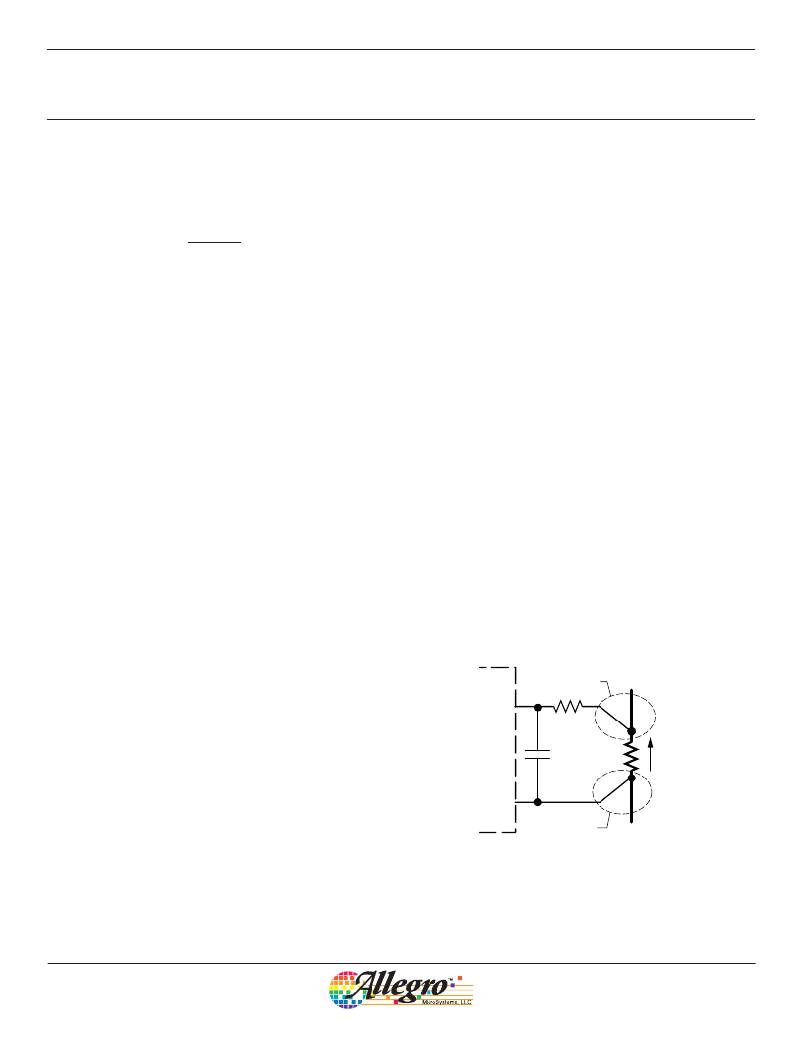
�ISEN�
�Kelvin�
�connection�
�temperature� within� the� safe� operating� area� for� the� device.�
�To� minimize� the� heating� effects� from� the� A4403� on� the� diode� and�
�vice-versa,� it� is� recommended� that� the� diode� be� mounted� on� the�
�reverse� side� of� the� printed� circuit� board.�
�A4403�
�R� FILTER�
�47� Ω�
�R� SENSE�
�C� FILTER�
�1� nF�
�Power�
�current�
�Sense� Resistor� The� sense� resistor� should� be� a� surface� mount�
�package,� with� low� inductance.� On� no� account� should� a� wire-�
�wound� or� through� hole� package� be� used.� To� prevent� potential�
�mistriggering� problems� from� occurring� in� noisy� systems,� it� is�
�recommended� that� an� R-C� filter� be� applied� across� the� sense� resis-�
�tor,� as� shown� in� figure� 3.�
�SGND�
�Kelvin�
�connection�
�Figure� 3.� R-C� filter� added� to� the� current� sense� circuit�
�Allegro� MicroSystems,� LLC�
�115� Northeast� Cutoff�
�Worcester,� Massachusetts� 01615-0036� U.S.A.�
�1.508.853.5000;� www.allegromicro.com�
�10�
�相关PDF资料 |
PDF描述 |
|---|---|
| AT88CK9000-TSU | CRYPTO PROGRAMMER BOARD 3-SOT23 |
| AT25080A-10TU-1.8 | IC EEPROM 8KBIT 20MHZ 8TSSOP |
| 8EWS12STRL | DIODE STD REC 1200V 8A D-PAK |
| AT25040AN-10SU-2.7 | IC EEPROM 4KBIT 20MHZ 8SOIC |
| 8EWS10STRL | DIODE STD REC 1000V 8A D-PAK |
相关代理商/技术参数 |
参数描述 |
|---|---|
| APEK4447SLJ-01-T-DK | 功能描述:A4447 - DC/DC, Step Down 1, Non-Isolated Outputs Evaluation Board 制造商:allegro microsystems, llc 系列:- 零件状态:有效 主要用途:DC/DC,步降 输出和类型:1,非隔离 功率 - 输出:- 电压 - 输出:0.8 V ~ 24 V 电流 - 输出:2A 电压 - 输入:8 V ~ 50 V 稳压器拓扑:降压 频率 - 开关:- 板类型:完全填充 所含物品:板 使用的 IC/零件:A4447 标准包装:1 |
| APEK4490EES-01-T-DK | 功能描述:BOARD EVAL FOR A4490 RoHS:是 类别:编程器,开发系统 >> 评估板 - DC/DC 与 AC/DC(离线)SMPS 系列:- 标准包装:1 系列:- 主要目的:DC/DC,步降 输出及类型:1,非隔离 功率 - 输出:- 输出电压:3.3V 电流 - 输出:3A 输入电压:4.5 V ~ 28 V 稳压器拓扑结构:降压 频率 - 开关:250kHz 板类型:完全填充 已供物品:板 已用 IC / 零件:L7981 其它名称:497-12113STEVAL-ISA094V1-ND |
| APEK4491EES-01-T-DK | 功能描述:A4491 - DC/DC, Step Down 3, Non-Isolated Outputs Evaluation Board 制造商:allegro microsystems, llc 系列:- 零件状态:有效 主要用途:DC/DC,步降 输出和类型:3,非隔离 功率 - 输出:- 电压 - 输出:- 电流 - 输出:- 电压 - 输入:4.5 V ~ 23 V 稳压器拓扑:降压 频率 - 开关:550kHz 板类型:完全填充 所含物品:板 使用的 IC/零件:A4491 标准包装:1 |
| APEK4900KLQ-01-T-DK | 功能描述:A4900 - Power Management, Half H-Bridge Driver (External FET) Evaluation Board 制造商:allegro microsystems, llc 系列:- 零件状态:过期 主要用途:电源管理,半 H 桥驱动器(外部 FET) 嵌入式:- 使用的 IC/零件:A4900 主要属性:3 个半 H 桥驱动器 辅助属性:- 所含物品:板 标准包装:1 |
| APEK4910KJP-01-T-DK | 功能描述:A4910 - Power Management, Half H-Bridge Driver (External FET) Evaluation Board 制造商:allegro microsystems, llc 系列:- 零件状态:有效 主要用途:电源管理,半 H 桥驱动器(外部 FET) 嵌入式:- 使用的 IC/零件:A4910 主要属性:3 个半 H 桥驱动器 辅助属性:- 所含物品:板 标准包装:1 |
发布紧急采购,3分钟左右您将得到回复。