- 您现在的位置:买卖IC网 > PDF目录51266 > APT50GT60S 110 A, 600 V, N-CHANNEL IGBT PDF资料下载
参数资料
| 型号: | APT50GT60S |
| 元件分类: | IGBT 晶体管 |
| 英文描述: | 110 A, 600 V, N-CHANNEL IGBT |
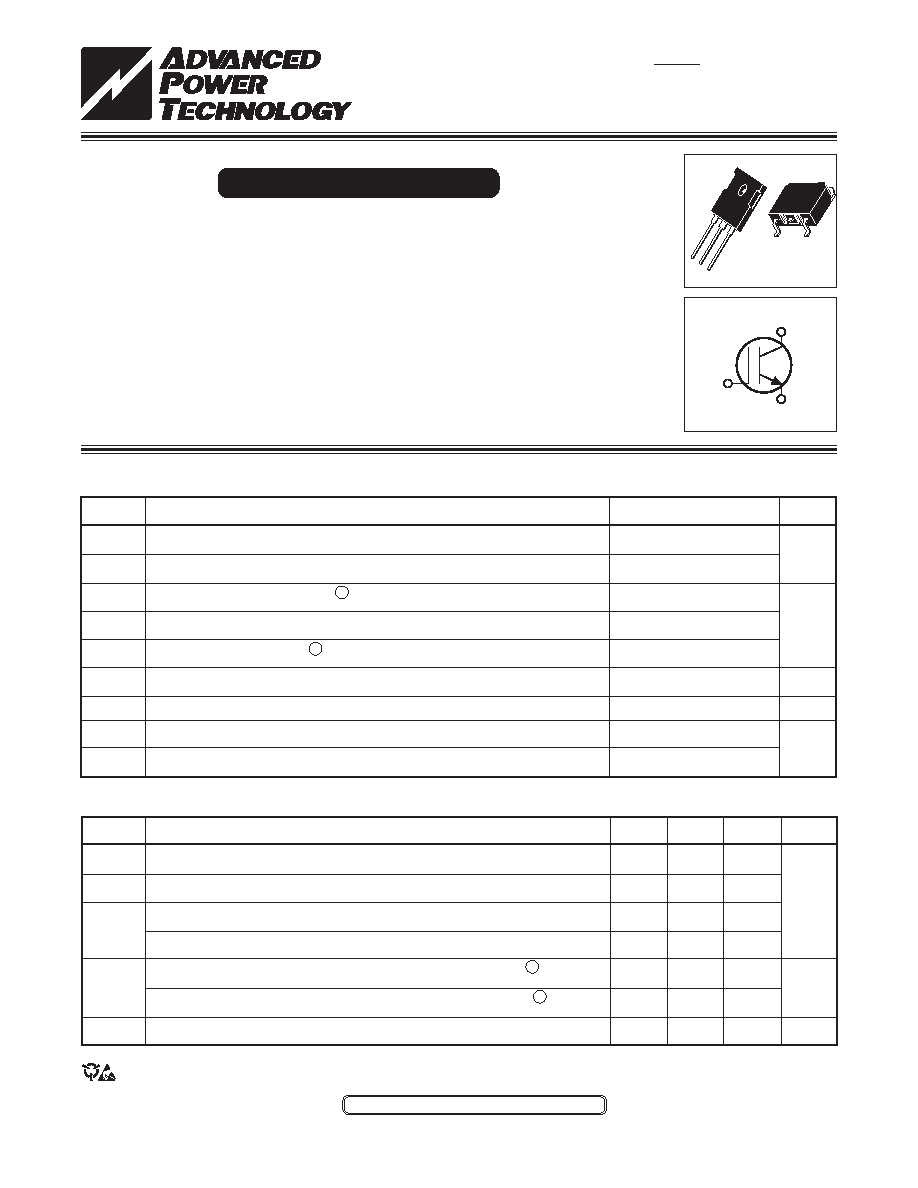
| 封装: | D3PAK-3 |
| 文件页数: | 1/6页 |
| 文件大小: | 409K |
| 代理商: | APT50GT60S |
052-6273
Rev
B
11-2005
APT50GT60B_SR(G)
TYPICAL PERFORMANCE CURVES
The Thunderblot IGBT is a new generation of high voltage power IGBTs. Using Non- Punch
Through Technology, the Thunderblot IGBT offers superior ruggedness and ultrafast
switching speed.
Low Forward Voltage Drop
High Freq. Switching to 100KHz
Low Tail Current
Ultra Low Leakage Current
RBSOA and SCSOA Rated
Thunderbolt IGBT
MAXIMUM RATINGS
All Ratings: T
C = 25°C unless otherwise specied.
STATIC ELECTRICAL CHARACTERISTICS
Characteristic / Test Conditions
Collector-Emitter Breakdown Voltage (V
GE = 0V, I C = 2mA)
Gate Threshold Voltage (V
CE = VGE, I C = 1mA, Tj = 25°C)
Collector-Emitter On Voltage (V
GE = 15V, IC = 50A, Tj = 25°C)
Collector-Emitter On Voltage (V
GE = 15V, IC = 50A, Tj = 125°C)
Collector Cut-off Current (V
CE = 600V, VGE = 0V, Tj = 25°C)
2
Collector Cut-off Current (V
CE = 600V, VGE = 0V, Tj = 125°C)
2
Gate-Emitter Leakage Current (V
GE = ±20V)
Symbol
V
(BR)CES
V
GE(TH)
V
CE(ON)
I
CES
I
GES
Units
Volts
A
nA
Symbol
V
CES
V
GE
I
C1
I
C2
I
CM
SSOA
P
D
T
J,TSTG
T
L
APT50GT60B_SR(G)
600
±30
110
52
150
150A @ 600V
446
-55 to 150
300
UNIT
Volts
Amps
Watts
°C
Parameter
Collector-Emitter Voltage
Gate-Emitter Voltage
Continuous Collector Current 7 @ T
C = 25°C
Continuous Collector Current @ T
C = 110°C
Pulsed Collector Current 1
Switching Safe Operating Area @ T
J = 150°C
Total Power Dissipation
Operating and Storage Junction Temperature Range
Max. Lead Temp. for Soldering: 0.063" from Case for 10 Sec.
APT Website - http://www.advancedpower.com
CAUTION: These Devices are Sensitive to Electrostatic Discharge. Proper Handling Procedures Should Be Followed.
MIN
TYP
MAX
600
3
4
5
1.7
2.0
2.5
2.2
25
TBD
120
G
C
E
TO-2
47
G
C
E
D3PAK
G
C
E
(S)
(B)
600V
APT50GT60B
APT50GT60S
APT50GT60BG* APT50GT60SG*
*G Denotes RoHS Compliant, Pb Free Terminal Finish.
相关PDF资料 |
PDF描述 |
|---|---|
| APT50GT60SG | 110 A, 600 V, N-CHANNEL IGBT |
| APT50GT60BRDL | 110 A, 600 V, N-CHANNEL IGBT, TO-247AD |
| APT50GT60BR | 110 A, 600 V, N-CHANNEL IGBT, TO-247AD |
| APT50GT60BRG | 110 A, 600 V, N-CHANNEL IGBT, TO-247AD |
| APT50GT60SRG | 110 A, 600 V, N-CHANNEL IGBT |
相关代理商/技术参数 |
参数描述 |
|---|---|
| APT50GT60SR | 制造商:ADPOW 制造商全称:Advanced Power Technology 功能描述:Thunderbolt IGBT |
| APT50GT60SRG | 制造商:ADPOW 制造商全称:Advanced Power Technology 功能描述:Thunderbolt IGBT |
| APT50M38JFLL | 功能描述:MOSFET N-CH 500V 88A SOT-227 RoHS:是 类别:半导体模块 >> FET 系列:POWER MOS 7® 标准包装:10 系列:* |
| APT50M38JFLL_04 | 制造商:MICROSEMI 制造商全称:Microsemi Corporation 功能描述:POWER MOS 7 R FREDFET |
| APT50M38JLL | 功能描述:MOSFET N-CH 500V 88A SOT-227 RoHS:是 类别:半导体模块 >> FET 系列:POWER MOS 7® 标准包装:10 系列:* |
发布紧急采购,3分钟左右您将得到回复。