- 您现在的位置:买卖IC网 > PDF目录48375 > ARF1510 4 CHANNEL, VHF BAND, Si, N-CHANNEL, RF POWER, MOSFET PDF资料下载
参数资料
| 型号: | ARF1510 |
| 元件分类: | 功率晶体管 |
| 英文描述: | 4 CHANNEL, VHF BAND, Si, N-CHANNEL, RF POWER, MOSFET |
| 文件页数: | 2/2页 |
| 文件大小: | 83K |
| 代理商: | ARF1510 |
050-4926
Rev
B
1-2005
DYNAMIC CHARACTERISTICS
ARF1510
Symbol
C
iss
C
oss
C
rss
t
d(on)
t
r
t
d(off)
t
f
Characteristic
Input Capacitance
Output Capacitance
Reverse Transfer Capacitance
Turn-on Delay Time
Rise Time
Turn-off Delay Time
Fall Time
Test Conditions
V
GS = 0V
V
DS = 200V
f = 1 MHz
V
GS = 15V
V
DD = 500V
I
D = 6.5A @ 25°C
R
G = 1.6
MIN
TYP
MAX
1200
1800
100
130
20
26
8
5
18
10
UNIT
pF
ns
FUNCTIONAL CHARACTERISTICS
Symbol
G
PS
η
ψ
Test Conditions
f = 40.7 MHz
V
GS = 0V
V
DD = 400V
Pout = 750W
No Degradation in Output Power
Characteristic
Common Source Amplifier Power Gain
Drain Efficiency
Electrical Ruggedness VSWR 6:1
MIN
TYP
MAX
13
15
75
UNIT
dB
%
1 Pulse Test: Pulse width < 380 S, Duty Cycle < 2%.
APT Reserves the right to change, without notice, the specifications and information contained herein.
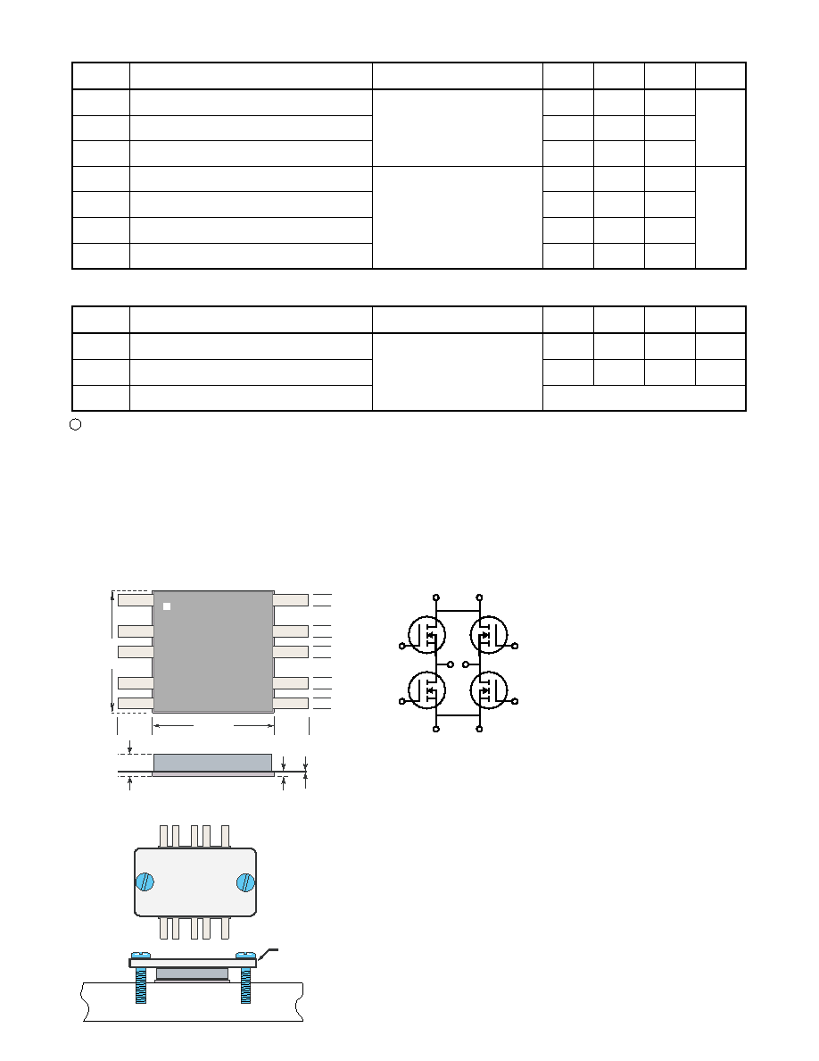
Thermal Considerations and Package Mounting:
The rated 1500W power dissipation is only available when the package mounting
surface is at 25°C and the junction temperature is 200°C. The thermal resistance
between junctions and case mounting surface is 0.12°C/W. When installed, and
additional thermal impedance of 0.08°C/W between the package base and the mounting
surface is typical. Insure that the mounting surface is smooth and flat. Thermal joint
compound must be used to reduce the effects of small surface irregularities. The heat
sink should incorporate a copper heat spreader to obtain best results.
The package is designed to be clamped to a heatsink. A clamped joint maintains
the required mounting pressure while allowing for thermal expansion of both the device
and the heat sink. A simple clamp and two 6-32 (M3.5) screw can provide the minimum
125lb required mounting force. T = 12 in-lb.
HAZARDOUS MATERIAL
WARNING
The ceramic portion of the device
between leads and mounting surface
is beryllium oxide, BeO. Beryllium
oxide dust is toxic when inhaled.
Care must be taken during handling
and mounting to avoid damage to
this area. These devices must never
be thrown away with general industri-
al or domestic waste.
D1
S1D2
G1
G2
S2
D3
G3
S3D4
G4
S4
ARF 1510
Clamp
Heat Sink
ARF1510
1.065"
27.05 mm
1.065"
27.05 mm
.100
.300
.100
.175
.075
.100
.175
.075
D1
S1D2
G1
G2
S2
D3
G3
S3D4
G4
S4
.005
.045
.254
相关PDF资料 |
PDF描述 |
|---|---|
| ARF442 | 8 A, 300 V, N-CHANNEL, Si, POWER, MOSFET, TO-247AD |
| ARF443 | 8 A, 300 V, N-CHANNEL, Si, POWER, MOSFET, TO-247AD |
| ARF464B | VHF BAND, Si, N-CHANNEL, RF POWER, MOSFET, TO-247 |
| ARF464A | VHF BAND, Si, N-CHANNEL, RF POWER, MOSFET, TO-247 |
| ARF465A | VHF BAND, Si, N-CHANNEL, RF POWER, MOSFET, TO-247AD |
相关代理商/技术参数 |
参数描述 |
|---|---|
| ARF1511 | 制造商:Microsemi Corporation 功能描述:RF MOSFET (VDMOS) - Bulk 制造商:Microsemi Corporation 功能描述:RF POWER TRANSISTOR MOSFET |
| ARF1518 | 制造商:ADPOW 制造商全称:Advanced Power Technology 功能描述:RF POWER MOSFET |
| ARF1519 | 制造商:Microsemi Corporation 功能描述:RF MOSFET (VDMOS) - Bulk |
| ARF1519G | 制造商:Microsemi Corporation 功能描述:RF POWER TRANSISTOR MOSFET |
| ARF1577 | 制造商:AMPHENOL 制造商全称:AMPHENOL 功能描述:RIGHT ANGLE PLUG JUMPER |
发布紧急采购,3分钟左右您将得到回复。