- 您现在的位置:买卖IC网 > Datasheet目录311 > AS5140 PB (ams)BOARD PROGRAM AS5140 Datasheet资料下载
参数资料
| 型号: | AS5140 PB |
| 厂商: | ams |
| 文件页数: | 16/38页 |
| 文件大小: | 0K |
| 描述: | BOARD PROGRAM AS5140 |
| 标准包装: | 1 |
| 模块/板类型: | 插槽适配器 |
| 适用于相关产品: | AS5000 编程器,AS5140 |
| 其它名称: | AS5140H PB-ND |
第1页第2页第3页第4页第5页第6页第7页第8页第9页第10页第11页第12页第13页第14页第15页当前第16页第17页第18页第19页第20页第21页第22页第23页第24页第25页第26页第27页第28页第29页第30页第31页第32页第33页第34页第35页第36页第37页第38页
�� �
�
�AS5140H�
�Data� Sheet� -� D� e� t� a� i� l� e� d� D� e� s� c� r� i� p� t� i� o� n�
�Programming� Daisy� Chained� Devices.� In� Daisy� Chain� mode,� the� Prog� pin� is� connected� directly� to� the� DO� pin� of� the� subsequent� device� in�
�the� chain� (see� Figure� 6)� .� During� programming� (see� Programming� the� AS5140H� on� page� 19)� ,� a� programming� voltage� of� 7.5V� must� be� applied� to�
�pin� Prog.� This� voltage� level� exceeds� the� limits� for� pin� DO,� so� one� of� the� following� precautions� must� be� made� during� programming:�
�Open� the� connection� DO� →� Prog� during� programming,� (or)�
�Add� a� Schottky� diode� between� DO� and� Prog� (Anode� =� DO,� Cathode� =� Prog)�
�Due� to� the� parallel� connection� of� CLK� and� CSn,� all� connected� devices� may� be� programmed� simultaneously.�
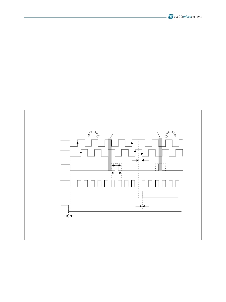
�7.2� Incremental� Outputs�
�Three� different� incremental� output� modes� are� possible� with� quadrature� A/B� being� the� default� mode.� Figure� 8� shows� the� two-channel� quadrature�
�as� well� as� the� step� /� direction� incremental� signal� (LSB)� and� the� direction� bit� in� clockwise� (CW)� and� counter-clockwise� (CCW)� direction.�
�7.2.1�
�Quadrature� A/B� Output� (Quad� A/B� Mode)�
�The� phase� shift� between� channel� A� and� B� indicates� the� direction� of� the� magnet� movement.� Channel� A� leads� channel� B� at� a� clockwise� rotation� of�
�the� magnet� (top� view)� by� 90� electrical� degrees.� Channel� B� leads� channel� A� at� a� counter-clockwise� rotation.�
�Figure� 8.� Incremental� Output� Modes�
�Quad� A/B-Mode�
�Mechanical�
�Zero� Position�
�Rotation� Direction�
�Change�
�Mechanical�
�Zero� Position�
�A�
�B�
�7.2.2�
�Index�
�Step� /� Dir-Mode�
�LSB�
�Dir�
�CSn�
�t� Incremental� outputs� valid�
�LSB� Output� (Step/Direction� Mode)�
�Clockwise� cw�
�Index=0�
�1� LSB�
�Index=1�
�3� LSB�
�Hyst=�
�2LSB�
�t� Dir� valid�
�Counterclockwise� ccw�
�Output� LSB� reflects� the� LSB� (least� significant� bit)� of� the� programmed� incremental� resolution� (OTP� Register� Bit� Div0,� Div1).� Output� Dir� provides�
�information� about� the� rotational� direction� of� the� magnet,� which� may� be� placed� above� or� below� the� device� (1=clockwise;� 0=counter� clockwise;� top�
�view).� Dir� is� updated� with� every� LSB� change.� In� both� modes� (quad� A/B,� step/direction),� the� resolution� and� the� index� output� are� user�
�programmable.� The� index� pulse� indicates� the� zero� position� and� is� by� default� one� angular� step� (1LSB)� wide.� However,� it� can� be� set� to� three� LSBs�
�by� programming� the� Index-bit� of� the� OTP� register� accordingly� (see� Table� 20)� .�
�www.austriamicrosystems.com/AS5140H�
�Revision� 1.4�
�15� -� 37�
�相关PDF资料 |
PDF描述 |
|---|---|
| ASDMB-ADAPTER-KIT | ASDMB MEMSPEED P II OSC KIT |
| ASFLMPLP-ADAPTER-KIT | ASFLMPLP MEMSPEED P II OSC KIT |
| AT24C01-10SI-1.8 | IC EEPROM 1KBIT 400KHZ 8SOIC |
| AT24C01B-TSU-T | IC EEPROM 1KBIT 1MHZ SOT23-5 |
| AT24C02C-XHM-B | IC EEPROM 2KBIT 1MHZ 8TSSOP |
相关代理商/技术参数 |
参数描述 |
|---|---|
| AS5140-SS_EK_AB | 功能描述:AS5140 - Magnetic, Rotary Position Sensor Evaluation Board 制造商:ams 系列:- 零件状态:有效 传感器类型:磁性,旋转位置 感应范围:360° 接口:串行 灵敏度:- 电压 - 电源:5V 嵌入式:否 所含物品:板 使用的 IC/零件:AS5140 标准包装:1 |
| AS5140-SS_EK_DB | 功能描述:AS5140 - Magnetic, Rotary Position Sensor Evaluation Board 制造商:ams 系列:- 零件状态:有效 传感器类型:磁性,旋转位置 感应范围:360° 接口:USB 灵敏度:- 电压 - 电源:5V USB 或 9V 嵌入式:是,MCU,8 位 所含物品:板,线缆 使用的 IC/零件:AS5140 标准包装:1 |
| AS51430FLF | 制造商:TT Electronics / IRC 功能描述:AS51430FLF |
| AS51430HLF | 制造商:TT Electronics / IRC 功能描述:AS51430HLF |
| AS51430JLF | 制造商:TT Electronics / IRC 功能描述:AS51430JLF |
发布紧急采购,3分钟左右您将得到回复。