- 您现在的位置:买卖IC网 > PDF目录256122 > BX80546PG2800E (INTEL CORP) 32-BIT, 2800 MHz, MICROPROCESSOR, CPGA478 PDF资料下载
参数资料
| 型号: | BX80546PG2800E |
| 厂商: | INTEL CORP |
| 元件分类: | 微控制器/微处理器 |
| 英文描述: | 32-BIT, 2800 MHz, MICROPROCESSOR, CPGA478 |
| 封装: | 1.27 MM PITCH, FLIP CHIP, MICRO PGA-478 |
| 文件页数: | 15/80页 |
| 文件大小: | 1845K |
| 代理商: | BX80546PG2800E |
第1页第2页第3页第4页第5页第6页第7页第8页第9页第10页第11页第12页第13页第14页当前第15页第16页第17页第18页第19页第20页第21页第22页第23页第24页第25页第26页第27页第28页第29页第30页第31页第32页第33页第34页第35页第36页第37页第38页第39页第40页第41页第42页第43页第44页第45页第46页第47页第48页第49页第50页第51页第52页第53页第54页第55页第56页第57页第58页第59页第60页第61页第62页第63页第64页第65页第66页第67页第68页第69页第70页第71页第72页第73页第74页第75页第76页第77页第78页第79页第80页
22
Datasheet
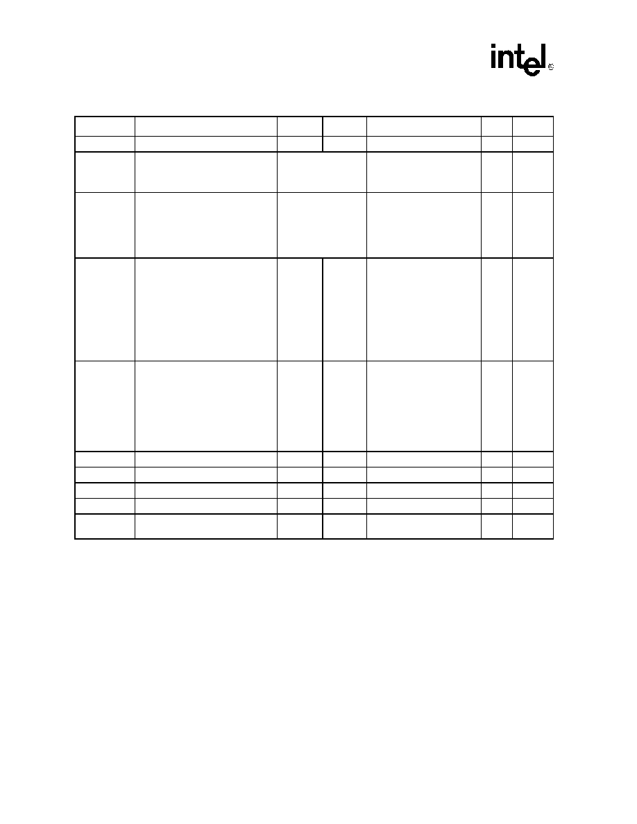
Electrical Specifications
Table 9.
Voltage and Current Specifications
Symbol
Parameter
Min
Typ
Max
Unit
Notes1
VID range
VID
1.250
1.400
V
2
V
CC
V
CC Loadline A processors
3.20E GHz (PRB = 1)
3.40E GHz (PRB = 1)
See Table 10 and
VID – I
CC(max) * 1.45 m
V
V
CC
V
CC Loadline B processors
2.80A/E GHz (PRB = 0)
3E GHz (PRB = 0)
3.20E GHz (PRB = 0)
3.40E GHz (PRB = 0)
See Table 11 and
VID – I
CC(max) * 1.45 m
V
3,4,5
I
CC
I
CC for processor with multiple VID:
2.80A/E GHz (PRB = 0)
3E GHz (PRB = 0)
3.20E GHz (PRB = 0)
3.40E GHz (PRB = 0)
3.20E GHz (PRB = 1)
3.40E GHz (PRB = 1)
78
91
A
6
ISGNT
ISLP
I
CC Stop-Grant:
2.80A/E GHz (PRB = 0)
3E GHz (PRB = 0)
3.20E GHz (PRB = 0)
3.40E GHz (PRB = 0)
3.20E GHz (PRB = 1)
3.40E GHz (PRB = 1)
40
50
A
7,8,10
I
TCC
I
CC TCC active
I
CC
A
9
I
CC
_VCCA
I
CC for PLL pins
60
mA
10
I
CC
_VCCIOPLL
I
CC for I/O PLL pin
60
mA
I
CC
_GTLREF
I
CC for GTLREF pins (all pins)
200
A
I
CC
_VCCVID/
VCCVIDLB
I
CC for V
CCVID/VCCVIDLB
150
mA
NOTES:
1.
Unless otherwise noted, all specifications in this table are based on estimates and simulations or empirical data.
2.
Individual processor VID values may be calibrated during manufacturing such that two devices at the same speed may have
different VID settings.
3.
These voltages are targets only. A variable voltage source should exist on systems in the event that a different voltage is re-
quired. See Section 2.3 and Table 3 for more information.
4.
The voltage specification requirements are measured across VCC_SENSE and VSS_SENSE pins at the socket with a
100 MHz bandwidth oscilloscope, 1.5 pF maximum probe capacitance, and 1 M
minimum impedance. The maximum length
of ground wire on the probe should be less than 5 mm. Ensure external noise from the system is not coupled into the oscillo-
scope probe.
5.
CC allowed for a given current. The
processor should not be subjected to any V
CC and ICC combination wherein VCC exceeds VCC
_MAX for a given current. Moreover,
V
CC should never exceed the VID voltage. Failure to adhere to this specification can shorten the processor lifetime.
6.
I
CC
_MAX is specified at VCC_MAX
7.
The current specified is also for the AutoHALT State.
8.
ICC Stop-Grant and ICC Sleep are specified at VCC_MAX.
9.
The maximum instantaneous current the processor will draw while the thermal control circuit is active as indicated by the as-
sertion of PROCHOT# is the same as the maximum I
CC for the processor.
相关PDF资料 |
PDF描述 |
|---|---|
| BU-61559D1-260S | 2 CHANNEL(S), 1M bps, MIL-STD-1553 CONTROLLER, CQIP78 |
| BU-61559D1-270Y | 2 CHANNEL(S), 1M bps, MIL-STD-1553 CONTROLLER, CQIP78 |
| BU-61559D1-510K | 2 CHANNEL(S), 1M bps, MIL-STD-1553 CONTROLLER, CQIP78 |
| BU-61559D1-600W | 2 CHANNEL(S), 1M bps, MIL-STD-1553 CONTROLLER, CQIP78 |
| BU-61559D1-740W | 2 CHANNEL(S), 1M bps, MIL-STD-1553 CONTROLLER, CQIP78 |
相关代理商/技术参数 |
参数描述 |
|---|---|
| BX80546PG3000E S L7PM | 制造商:Intel 功能描述: |
| BX80546PG3000E S L8JZ | 制造商:Intel 功能描述: |
| BX80546PG3200E | 制造商:Intel 功能描述:MPU PENTIUM 4 PROCESSOR NETBURST 90NM 3.2GHZ - Boxed Product (Development Kits) |
| BX80546PG3200E S L8K2 | 制造商:Intel 功能描述: |
| BX80546PG3400E | 制造商:Intel 功能描述:MPU PENTIUM 4 PROCESSOR NETBURST 90NM 3.4GHZ - Boxed Product (Development Kits) |
发布紧急采购,3分钟左右您将得到回复。