- 您现在的位置:买卖IC网 > PDF目录16231 > CDB5463U (Cirrus Logic Inc)BOARD EVAL & SOFTWARE CS5463 ADC PDF资料下载
参数资料
| 型号: | CDB5463U |
| 厂商: | Cirrus Logic Inc |
| 文件页数: | 14/46页 |
| 文件大小: | 0K |
| 描述: | BOARD EVAL & SOFTWARE CS5463 ADC |
| 标准包装: | 1 |
| 主要目的: | 电源管理,电度表/功率表 |
| 嵌入式: | 是,MCU,8 位 |
| 已用 IC / 零件: | CS5463 |
| 主要属性: | 1 相,能量至频率输出 |
| 次要属性: | GUI、USB、SPI 接口 |
| 已供物品: | 板 |
| 产品目录页面: | 754 (CN2011-ZH PDF) |
| 相关产品: | CS5463-ISZR-ND - IC ENERGY METERING 1PHASE 24SSOP 598-1192-5-ND - IC PWR/ENERGY METER 2CH 24-SSOP 598-1096-5-ND - IC ENERGY METERING 1PHASE 24SSOP |
| 其它名称: | 598-1553 |
第1页第2页第3页第4页第5页第6页第7页第8页第9页第10页第11页第12页第13页当前第14页第15页第16页第17页第18页第19页第20页第21页第22页第23页第24页第25页第26页第27页第28页第29页第30页第31页第32页第33页第34页第35页第36页第37页第38页第39页第40页第41页第42页第43页第44页第45页第46页
�� �
�
�CS5463�
�Digital� Filter�
�V� DCoff� *� V� gn� *�
�APF�
�VOLTAGE�
�x10�
�2nd� Order�
�??�
�Modulator�
�DELAY�
�REG�
�SINC� 3�
�X�
�DELAY�
�REG�
�IIR�
�+�
�?�
�+�
�X�
�HPF�
�V*�
�V� Q� *�
�X�
�+�
�?�
�X�
�Q*�
�6�
�?� *�
�X�
�+�
�?�
�PC6� PC5� PC4� PC3� PC2� PC1� PC0�
�Configuration� Register� *�
�SYS� Gain� *�
�2322�
�...� XVDEL� XIDEL� VHPF� IHPF�
�8� 7� 6� 5�
�Operational� Modes� Register� *�
�IIR�
�4�
�3� 2� 1� 0�
�X�
�P*�
�2� ?�
�X�
�?�
�CURRENT�
�PGA�
�4th� Order�
�??�
�Modulator�
�SINC� 3�
�DELAY�
�REG�
�Digital� Filter�
�DELAY�
�REG�
�IIR�
�+�
�+�
�I� DCoff� *�
�X�
�I� gn� *�
�HPF�
�APF�
�I*�
�*� DENOTES� REGISTER� NAME.�
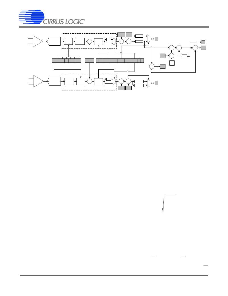
�Figure� 3.� Data� Measurement� Flow� Diagram.�
�4.� THEORY� OF� OPERATION�
�The� CS5463� is� a� dual-channel� analog-to-digital� convert-�
�er� (ADC)� followed� by� a� computation� engine� that� per-�
�forms� power� calculations� and� energy-to-pulse�
�conversion.� The� data� flow� for� the� voltage� and� current�
�channel� measurement� and� the� power� calculation� algo-�
�rithms� are� depicted� in� Figure� 3� and� 4,� respectively.�
�The� analog� inputs� are� structured� with� two� dedicated�
�channels,� Voltage� and� Current� ,� then� optimized� to� simpli-�
�fy� interfacing� to� various� sensing� elements.�
�The� voltage-sensing� element� introduces� a� voltage�
�waveform� on� the� voltage� channel� input� VIN±� and� is� sub-�
�ject� to� a� gain� of� 10x.� A� second-order� delta-sigma� modu-�
�lator� samples� the� amplified� signal� for� digitization.�
�Simultaneously,� the� current-sensing� element� introduces�
�a� voltage� waveform� on� the� current� channel� input� IIN±�
�and� is� subject� to� two� selectable� gains� of� the� program-�
�mable� gain� amplifier� (PGA).� The� amplified� signal� is�
�sampled� by� a� fourth-order� delta-sigma� modulator� for�
�from� the� calculated� V� RMS� and� I� RMS� as� well� as� the� appar-�
�ent� power.�
�When� the� optional� HPF� in� either� channel� is� disabled,� an�
�all-pass� filter� (APF)� is� implemented.� The� APF� has� an�
�amplitude� response� that� is� flat� within� the� channel� band-�
�width� and� is� used� for� matching� phase� in� systems� where�
�only� one� HPF� is� engaged.�
�4.2� Voltage� and� Current� Measurements�
�The� digital� filter� output� word� is� then� subject� to� a� DC� off-�
�set� adjustment� and� a� gain� calibration� (See� Section� 7.�
�System� Calibration� on� page� 37).� The� calibrated� mea-�
�surement� is� available� by� reading� the� instantaneous� volt-�
�age� and� current� registers.�
�The� Root� Mean� Square� (� RMS� in� Figure� 4)� calculations�
�are� performed� on� N� instantaneous� voltage� and� current�
�samples,� V� n� and� I� n� ,� respectively� (where� N� is� the� cycle�
�count),� using� the� formula:�
�digitization.� Both� converters� sample� at� a� rate� of�
�MCLK/8,� the� over-sampling� provides� a� wide� dynamic�
�range� and� simplified� anti-alias� filter� design.�
�4.1� Digital� Filters�
�I� RMS� =�
�N� –� 1�
�?� In�
�n� =� 0�
�---------------------�
�N�
�The� decimating� digital� filters� on� both� channels� are� Sinc� 3�
�filters� followed� by� 4th-order� IIR� filters.� The� single-bit�
�data� is� passed� to� the� low-pass� decimation� filter� and� out-�
�put� at� a� fixed� word� rate.� The� output� word� is� passed� to� an�
�optional� IIR� filter� to� compensate� for� the� magnitude� roll�
�off� of� the� low-pass� filtering� operation.�
�An� optional� digital� high-pass� filter� (� HPF� in� Figure� 3)� re-�
�moves� any� DC� component� from� the� selected� signal�
�path.� By� removing� the� DC� component� from� the� voltage�
�and/or� the� current� channel,� any� DC� content� will� also� be�
�removed� from� the� calculated� active� power� as� well.� With�
�both� HPFs� enabled� the� DC� component� will� be� removed�
�14�
�and� likewise� for� V� RMS� ,� using� V� n� .� I� RMS� and� V� RMS� are� ac-�
�cessible� by� register� reads,� which� are� updated� once� ev-�
�ery� cycle� count� (referred� to� as� a� computational� cycle).�
�4.3� Power� Measurements�
�The� instantaneous� voltage� and� current� samples� are�
�multiplied� to� obtain� the� instantaneous� power� (see� Fig-�
�ure� 3).� The� product� is� then� averaged� over� N� conver-�
�sions� to� compute� active� power� and� is� used� to� drive�
�energy� pulse� output� E1.� Energy� output� E2� is� selectable,�
�providing� an� energy� sign� or� a� pulse� output� that� is� pro-�
�portional� to� the� apparent� power.� Energy� output� E3�
�DS678F3�
�相关PDF资料 |
PDF描述 |
|---|---|
| 2474R-25L | INDUCTOR 100UH POWER AXIAL |
| EBA36DRXH | CONN EDGECARD .125 DIP 72POS |
| M3URK-2018R | IDC CABLE - MKS20K/MC20M/MPR20K |
| EET-UQ2G681KA | CAP ALUM 680UF 400V 20% SNAP |
| EMM06DRMI-S288 | CONN EDGECARD 12POS .156 EXTEND |
相关代理商/技术参数 |
参数描述 |
|---|---|
| CDB5463U-Z | 功能描述:EVAL BOARD USB FOR CS5463 RoHS:是 类别:编程器,开发系统 >> 评估板 - 模数转换器 (ADC) 系列:- 产品培训模块:Obsolescence Mitigation Program 标准包装:1 系列:- ADC 的数量:1 位数:12 采样率(每秒):94.4k 数据接口:USB 输入范围:±VREF/2 在以下条件下的电源(标准):- 工作温度:-40°C ~ 85°C 已用 IC / 零件:MAX11645 已供物品:板,软件 |
| CDB5464U | 功能描述:数据转换 IC 开发工具 Eval Bd 3-Ch Sngl-Phs Pow/Energy RoHS:否 制造商:Texas Instruments 产品:Demonstration Kits 类型:ADC 工具用于评估:ADS130E08 接口类型:SPI 工作电源电压:- 6 V to + 6 V |
| CDB5464U-Z | 制造商:Cirrus Logic 功能描述:EVAL BD PB-FREE DEMO BOARD FOR CS5464 - Boxed Product (Development Kits) 制造商:Cirrus Logic 功能描述:Eval Board |
| CDB5466U | 功能描述:数据转换 IC 开发工具 Eval Bd F/Residental Pow-Meter Apps RoHS:否 制造商:Texas Instruments 产品:Demonstration Kits 类型:ADC 工具用于评估:ADS130E08 接口类型:SPI 工作电源电压:- 6 V to + 6 V |
| CDB5466U-Z | 制造商:Cirrus Logic 功能描述:PB-FREEEVAL BOARD FOR CS5466 WITH USB - Bulk |
发布紧急采购,3分钟左右您将得到回复。