- 您现在的位置:买卖IC网 > PDF目录26498 > CDS-1401MM (MURATA POWER SOLUTIONS INC) PDF资料下载
参数资料
| 型号: | CDS-1401MM |
| 厂商: | MURATA POWER SOLUTIONS INC |
| 元件分类: | 取样保持放大器 |
| 中文描述: | SAMPLE AND HOLD AMPLIFIER, 0.35 us ACQUISITION TIME, CDIP24 |
| 封装: | CERAMIC, DDIP-24 |
| 文件页数: | 6/8页 |
| 文件大小: | 87K |
| 代理商: | CDS-1401MM |
6
CDS-1401
For most sampling A/D's, the rising edge of the start-convert
pulse drives the internal S/H into the hold mode under the
assumption the S/H has already fully acquired and is tracking
the input signal. In this case, the same edge can not be used
to drive S/H2 into the hold mode and simultaneously initiate the
A/D conversion. The output of S/H2 needs time to settle its
sample-to-hold switching transient, and the input S/H of the
A/D needs time to fully acquire its new input signal.
As shown in Figure 1, output line A/D CLOCK1 (pin 18) is a
slightly delayed version of the signal applied to pin 11 (S/H1
COMMAND), and A/D CLOCK1 (pin 17) is its complement.
A/D CLOCK2 (pin 19) is a delayed version of the signal applied
to pin 12 (S/H2 COMMAND), and A/D CLOCK2 (pin 20) is its
complement. Any one of these signals, as appropriate, may be
used to trigger the A/D conversion.
Figure 3 is a typical timing diagram for a CDS-1401 in front of
DATEL's 12-bit, 1.2MHz sampling A/D, the ADS-CCD1201.
less than that of video signals, it may not be necessary for the
allocated acquisition time of S/H1 to be as long as that of S/H2.
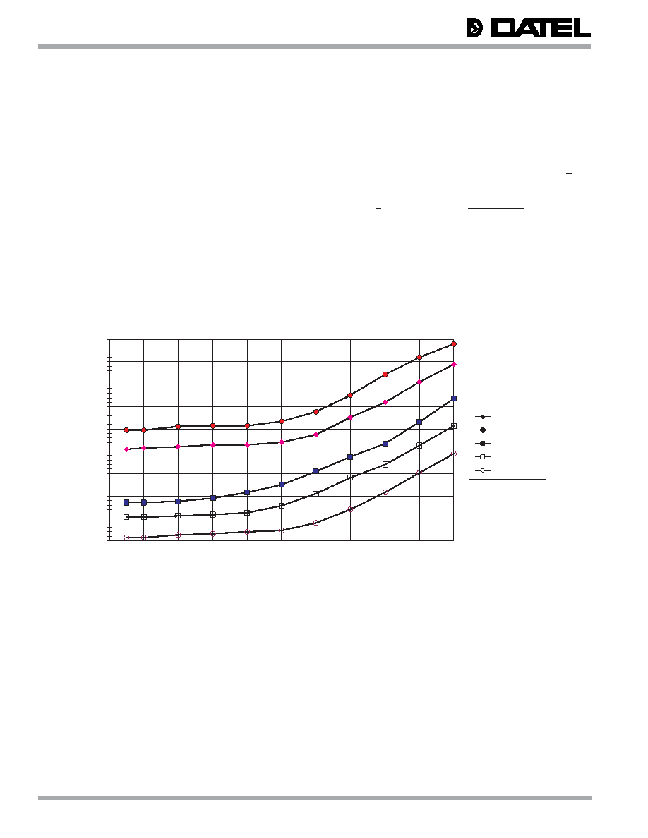
As shown in the plot (Figure 4) of acquisition times vs. input
signal step size, the S/H's internal to the CDS-1401 acquire
smaller-amplitude signals quicker than they acquire larger-
amplitude signals. In "maximum-throughput" applications,
assuming "asymmetric" timing can be accommodated, each
S/H should only be given the time it requires, and no more, to
acquire its input signal. Leaving a S/H amp in the sample
mode for a longer period of time has little added benefit.
As an example, the graph shows that it takes 160ns to acquire
a 500mV step to within 10mV of accuracy and 260ns to
acquire a 500mV step to within 0.5mV of accuracy. The figures
in this graph are typical values at room temperature.
The CDS-1401 brings out 4 control lines that can be used to
trigger an A/D converter connected to its output. If the A/D is
a sampling type, system timing should be such that the A/D's
input S/H amplifier is acquiring the output of the CDS-1401 at
the same time the output is settling to its final value.
Figure 4. Acquisition Time versus Accuracy and Step Size
160
180
200
220
240
260
280
300
320
340
012
34567
89
10
Input Step Size (Volts)
Acqui
si
tion
T
im
e(
ns)
±0.5mV accuracy
±1mV accuracy
±2mV accuracy
±5mV accuracy
±10mV accuracy
相关PDF资料 |
PDF描述 |
|---|---|
| CDS-1402MC | |
| CFUKF455KB4X-R0 | |
| CFUKF455KD1X-R0 | |
| CFULB455KB2A-B0 | |
| CFULB455KF4A-B0 | |
相关代理商/技术参数 |
参数描述 |
|---|---|
| CDS1402 | 制造商:未知厂家 制造商全称:未知厂家 功能描述:14-Bit, Very Fast Settling Correlated Double Sampling Circuit |
| CDS-1402 | 制造商:未知厂家 制造商全称:未知厂家 功能描述:14-Bit, Very Fast Settling Correlated Double Sampling Circuit |
| CDS-1402MC | 制造商:Murata Power Solutions 功能描述:Correlated Double Sampler (Cds) 24-Pin CDDIP |
| CDS-1402MM | 制造商:Murata Power Solutions 功能描述:Correlated Double Sampler (Cds) 24-Pin CDDIP |
| CDS14N | 功能描述:SOCKET,1/4" DRIVE,7MM,6PT 制造商:apex tool group 系列:* 零件状态:在售 标准包装:1 |
发布紧急采购,3分钟左右您将得到回复。