- 您现在的位置:买卖IC网 > PDF目录16103 > CIC-FILT-E2-UT2 (Lattice Semiconductor Corporation)SITE LICENSE CIC FILTER EC/ECP PDF资料下载
参数资料
| 型号: | CIC-FILT-E2-UT2 |
| 厂商: | Lattice Semiconductor Corporation |
| 文件页数: | 10/33页 |
| 文件大小: | 0K |
| 描述: | SITE LICENSE CIC FILTER EC/ECP |
| 标准包装: | 1 |
| 系列: | * |
| 其它名称: | CICFILTE2UT2 |
第1页第2页第3页第4页第5页第6页第7页第8页第9页当前第10页第11页第12页第13页第14页第15页第16页第17页第18页第19页第20页第21页第22页第23页第24页第25页第26页第27页第28页第29页第30页第31页第32页第33页
�� �
�
�Lattice� Semiconductor�
�Functional� Description�
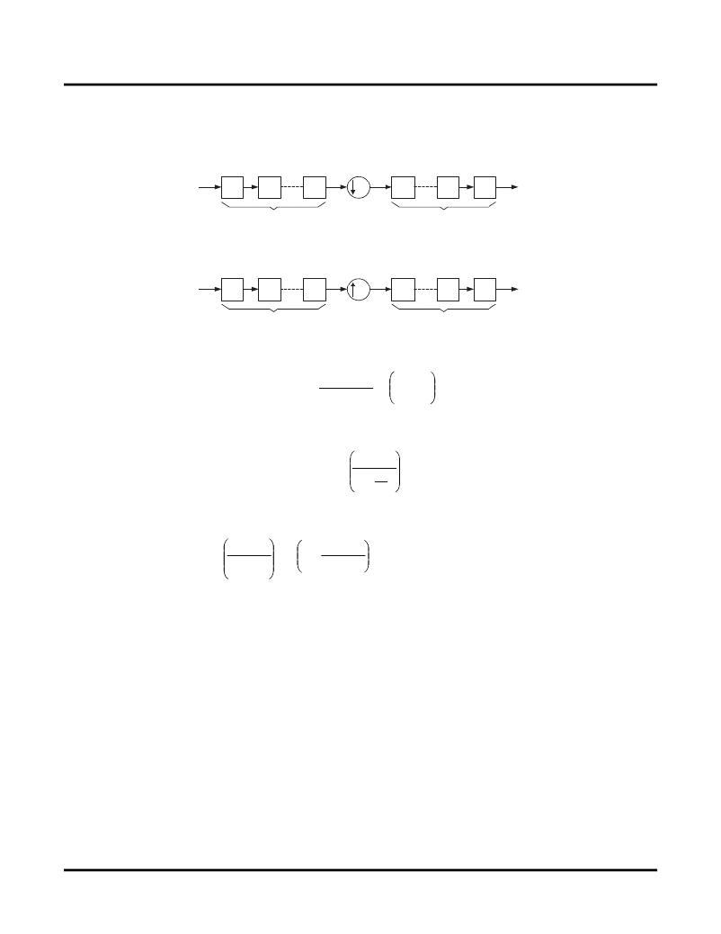
�A� CIC� decimator� and� interpolator� with� N� stages� are� shown� in� Figure� 2-2� ,� where� I� and� C� represent� an� integrator� and�
�a� comb,� respectively.� The� symbols,� ?� R� and� ?� R,� represent� down-sampling� and� up-sampling,� respectively.�
�Figure� 2-2.� CIC� Decimator� and� Interpolator�
�(a)� CIC� Decimator�
�x(n)�
�I�
�I�
�I�
�R�
�C�
�C�
�C�
�y(n)�
�(b)� CIC� Interpolator�
�N� Stages�
�N� Stages�
�x(n)�
�C�
�C�
�C�
�R�
�I�
�I�
�I�
�y(n)�
�N� Stages�
�N� Stages�
�The� system� transfer� function� of� the� CIC� decimator� and� interpolator� in� the� z-plane� is�
�?� z�
�H(z) =�
�(1� -� z� -RM� )� N�
�(1� -� z� -1� )� N�
�=�
�RM-1�
�k=0�
�-k�
�N�
�(1)�
�The� frequency� response� can� be� derived� by� substituting� z=j� 2?f� in� Equation� 1,� where� f� is� the� frequency� relative� to� the�
�low� sampling� rate,� f� S� /R.�
�?� f�
�H(f) =�
�sin� ?� Mf�
�sin�
�R�
�N�
�(2)�
�By� using� sin� xYx� for� small� x,� we� can� approximate� Equation� 2� for� a� large� R� as�
�sin� ?� Mf�
�?� f�
�N�
�H(f)� =� =� RM�
�sin� ?� Mf�
�?� Mf�
�N�
�=� [RMsinc(� ?� Mf)]� N�
�if� f� <<� M�
�(3)�
�R�
�Equation� 3� indicates� that� the� frequency� response� has� nulls� (zeros)� at� integer� multiples� of� f=1/M.�
�As� given� in� Equation� 3,� the� frequency� response� of� the� CIC� filter� resembles� a� sinc� waveform.� The� main� lobe� of� the�
�sinc� wave� is� the� passband� and� the� side� lobes� are� the� aliasing� or� imaging� bands.� The� parameters� N,� M,� and� R�
�decide� the� characteristics� of� the� passband� and� the� aliasing� bands.�
�Interfacing� with� the� CIC� Filter�
�To� ensure� proper� functioning� of� the� CIC� filter� for� different� usage� scenarios,� the� handshake� signals� must� be� correctly�
�used� and� the� rules� of� interfacing� must� be� followed.� For� a� CIC� filter,� the� input� and� output� data� rates� are� not� the� same�
�and� one� of� the� rates� is� higher� than� the� other� by� a� factor� of� R,� the� sampling� rate� factor.� For� multi-channel� operations,�
�the� channel� index� changes� more� frequently� than� the� data� index,� in� both� input� and� output� data� streams.� For� exam-�
�ple,� for� a� three-channel� decimator,� data� 0� of� channel� 0� is� followed� by� data� 0� of� channel� 1� and� data� 0� of� channel� 2.�
�After� data� 0� of� all� the� channels� are� applied,� data� 1� for� the� channels� follows.� For� easier� understanding,� the� terms�
�“input� data� cycle”� and� “output� data� cycle”� are� used� and� explained� for� each� case.�
�For� a� decimator,� R� input� samples� are� read� for� every� output� sample.� For� a� single-channel� decimator,� the� inputs� are�
�applied� sequentially� and� one� output� data� is� available� every� R� cycles.� Here� the� input� data� cycle� is� one� cycle� long�
�and� the� output� data� cycle� is� R� cycles� long.� The� availability� of� valid� output� data� is� indicated� by� the� outvalid� signal,�
�which� goes� high� for� the� first� clock� cycle� of� an� output� data� cycle.� There� could� be� arbitrary� breaks� in� the� input� data�
�IPUG42_02.6,� August� 2010�
�10�
�Cascaded� Integrator-Comb� (CIC)� Filter� User’s� Guide�
�相关PDF资料 |
PDF描述 |
|---|---|
| RYM08DTMS | CONN EDGECARD 16POS R/A .156 SLD |
| MAX6315US46D3+T | IC RESET CIRCUIT 4.63V SOT143-4 |
| RP15-4812SOFW/N-R | CONV DC/DC 15W 18-75VIN 12VOUT |
| MAX6315US44D3+T | IC RESET CIRCUIT 4.39V SOT143-4 |
| UWX1C101MCL1GB | CAP ALUM 100UF 16V 20% SMD |
相关代理商/技术参数 |
参数描述 |
|---|---|
| CIC-FILT-E3-U2 | 功能描述:开发软件 CASCADED INTEGRATOR COMB FILTER RoHS:否 制造商:Atollic Inc. 产品:Compilers/Debuggers 用于:ARM7, ARM9, Cortex-A, Cortex-M, Cortex-R Processors |
| CIC-FILT-E3-UT2 | 功能描述:开发软件 CASCADE INTEGRATOR COMB FILTER RoHS:否 制造商:Atollic Inc. 产品:Compilers/Debuggers 用于:ARM7, ARM9, Cortex-A, Cortex-M, Cortex-R Processors |
| CIC-FILT-P2-U2 | 功能描述:开发软件 Cascaded Integrator Comb Filter RoHS:否 制造商:Atollic Inc. 产品:Compilers/Debuggers 用于:ARM7, ARM9, Cortex-A, Cortex-M, Cortex-R Processors |
| CIC-FILT-P2-UT2 | 制造商:Lattice Semiconductor Corporation 功能描述: |
| CIC-FILT-PM-U2 | 功能描述:开发软件 Cascaded Integrator Comb Filter RoHS:否 制造商:Atollic Inc. 产品:Compilers/Debuggers 用于:ARM7, ARM9, Cortex-A, Cortex-M, Cortex-R Processors |
发布紧急采购,3分钟左右您将得到回复。