- 您现在的位置:买卖IC网 > Datasheet目录319 > CPD250-4530G (Power-One)PWR SUP 250W 3.3/5/12/-12V QUAD Datasheet资料下载
参数资料
| 型号: | CPD250-4530G |
| 厂商: | Power-One |
| 文件页数: | 17/19页 |
| 文件大小: | 0K |
| 描述: | PWR SUP 250W 3.3/5/12/-12V QUAD |
| 标准包装: | 20 |
| 系列: | CPD |
| 类型: | 隔离 |
| 输入电压: | 36 ~ 75V |
| 输出: | 5V,3.3V,±12V |
| 输出数: | 4 |
| 输出 - 1 @ 电流(最大): | 5 VDC @ 40A |
| 输出 - 2 @ 电流(最大): | 3.3 VDC @ 40A |
| 输出 - 3 @ 电流(最大): | 12 VDC @ 5.5A |
| 输出 - 4 @ 电流(最大): | -12 VDC @ 2A |
| 功率(瓦特): | 250W |
| 安装类型: | Compact PCI® |
| 效率: | 82.2% |
| 封装/外壳: | 模块 |
| 尺寸/尺寸: | 6.40" L x 1.60" W x 5.07" H(162.5mm x 40.6mm x 128.7mm) |
| 包装: | 散装 |
| 电源(瓦特)- 最大: | 250W |
| 批准: | CE,CSA,cUL,EN,TUV,UL |
| 产品目录页面: | 2739 (CN2011-ZH PDF) |
| 其它名称: | 179-2281 CPD250-4530-G |
�� ��
��
��CPA,� CPD� Series� Data� Sheet�
�?�
�200� –� 550� Watt�
�CompactPCI� ?�
�AC-DC� and� DC-DC� Converters�
�Safety� and� Installation� Instructions�
�Connector� Pin� Allocation�
�The� connector� pin� allocation� table� defines� the� electrical�
�potentials� and� the� physical� pin� positions� on� the� Positronic�
�connector.� Pin� no.� 45� (protective� earth)� is� a� leading� pin,�
�ensuring� that� it� makes� contact� with� the� female� connector� first.�
�Installation� Instructions�
�These� converters� are� components,� intended� exclusively� for�
�installation� within� other� equipment� by� an� industrial� assembly�
�process� or� by� a� professionally,� competent� person.� Installation�
�must� strictly� follow� the� national� safety� regulations� in� respect� of�
�the� enclosure,� mounting,� creepage� distances,� clearance,�
�casualty� markings,� and� segregation� requirements� of� the� end-�
�use� application.�
�Connection� to� the� system� shall� be� made� via� the� mating�
�female� connector� (see� fig.� 16).� Other� installation� methods�
�may� not� meet� the� safety� requirements.� Check� for� hazardous�
�voltage,� before� altering� any� connections.�
�Connector:� Positronic� PCIH47M400A1� or� similar�
�Mating� female� connector:� Positronic� PCIH47F300A1� or� similar�
�10087a�
�The� converters� are� provided� with� a� leading� pin� no.� 45,� which� is�
�reliably� connected� to� the� case.� For� safety� reasons� it� is�
�essential� to� connect� this� pin� to� the� protective� earth� of� the�
�supply� system.�
�The� input� –DCIN� or� ACL� (pin� no.� 47)� is� internally� fused;� see�
�Input� Fuse� and� Protection� .� This� fuse� is� designed� to� break� an�
�overcurrent� in� case� of� a� malfunction� of� the� converter� and� is� not�
�customer-accessible.�
�External� fuses� in� the� wiring� to� one� or� both� input� lines� (pin� 47�
�and/or� pin� 46)� may� be� necessary� to� ensure� compliance� with�
�local� requirements.� A� built-in� second� fuse� in� the� neutral� line�
�(pin� 47)� is� available� as� option� F� for� CPA500� models.�
�A� second� fuse� in� the� wiring� to� the� neutral� line� or� option� F� may�
�be� needed� if:�
�?� Local� requirements� demand� an� individual� fuse� in� each�
�source� line�
�?� Neutral� and� earth� impedance� is� high� or� undefined�
�?� Phase� and� neutral� of� the� mains� are� not� defined� or� cannot�
�be� assigned� to� the� corresponding� terminals.�
�Caution:�
�Installation� must� strictly� follow� the� national� safety� regulations.�
�Models� with� option� F:� Caution!� Double-pole/neutral� fusing.�
�Do� not� open� the� converters,� or� the� warranty� will� be� invalidated!�
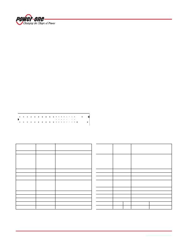
�1� 3� 5� 7� 9� 11� 13� 15� 17� 19� 21� 24� 27� 30� 33� 36� 39� 42�
�22� 25� 28� 31� 34� 37� 40� 43�
�46�
�Important:� If� the� inhibit� function� is� not� used,� pin� 39� (i)� should� be�
�left� open-circuit� to� enable� the� outputs.� Enable� Pin� 27� (EN#)�
�2� 4� 6� 8� 10� 12� 14� 16� 18� 20�
�23� 26� 29� 32� 35� 38� 41� 44�
�45�
�47�
�should� be� connected� to� pin� 22� (RTN)� to� enable� the� outputs.�
�Make� sure� that� there� is� sufficient� airflow� available� for�
�Fig.� 19�
�Pinout� of� the� front� connector�
�Table� 13:� Pin� allocation� of� the� front� connector�
�convection� cooling.� This� should� be� verified� by� measuring� the�
�case� temperature,� when� the� converter� is� installed� and�
�operated� in� the� end-use� application.� The� maximum� specified�
�case� temperature� T� C� max� should� not� be� exceeded.�
�Pin� 1�
�Length� 2� Signal�
�Description�
�Pin� 1� Length� 2� Signal�
�Description�
�name�
�name�
�1–4�
�B� Vo1�
�Output� 1�
�32� C�
�n.c.�
�Do� not� connect�
�5� –� 12�
�13� –� 18�
�19�
�20�
�21�
�22�
�23�
�24�
�25�
�26�
�27�
�28�
�29�
�30�
�31�
�B�
�B�
�B�
�B�
�C�
�C�
�C�
�C�
�C�
�C�
�D�
�C�
�C�
�C�
�C�
�RTN�
�Vo2�
�RTN�
�Vo3�
�Vo4�
�RTN�
�Reserved�
�RTN�
�n.c.�
�Reserved�
�EN� #�
�n.c.�
�n.c.�
�Vo1SENSE�
�n.c.�
�Return� (Vo1� and� Vo2)�
�Output� 2�
�Return� (Vo3)�
�Output� 3�
�Output� 4�
�Return�
�Reserved�
�Return� (Vo4)�
�Do� not� connect�
�Reserved�
�Enable�
�Do� not� connect�
�Do� not� connect�
�Vo1� remote� sense�
�Do� not� connect�
�33�
�34�
�35�
�36�
�37�
�38�
�39�
�40�
�41�
�42�
�43�
�44�
�45�
�46�
�47�
�C�
�C�
�C�
�C�
�C�
�C�
�C�
�C�
�C�
�C�
�C�
�C�
�A� 3�
�A�
�A�
�Vo2SENSE�
�SRTN�
�Vo1SHARE�
�Vo3SENSE�
�n.c.�
�DEG#�
�INH� #�
�n.c.�
�Vo2SHARE�
�FAL#�
�n.c.�
�Vo3SHARE�
�CGND�
�+DCIN� 4� ACN� 5�
�–DCIN� 4� ACL� 5�
�Vo2� remote� sense�
�Sense� return�
�Vo1� current� share�
�Vo3� remote� sense�
�Do� not� connect�
�Degrade� signal�
�Inhibit�
�Do� not� connect�
�Vo2� current� share�
�Fail� signal�
�Do� not� connect�
�Vo3� current� share�
�Chassis� ground�
�Pos.� DC� input� 4� Neutral� line� 5�
�Neg.� DC� input� 4� Line� input� (phase)� 5�
�1�
�2�
�3�
�4�
�5�
�Pin� numbers� shown� are� for� the� female� backplane� connector�
�A� =� very� long� pins,� B� =� long� pins,� C� =� short� pins,� D� =� very� short� pins.�
�Pin� 45� of� the� female� connector� is� leading,� ensuring� that� chassis� ground� makes� contact� first.�
�CPD� models� (DC� input)�
�CPA� models� (AC� input)�
�BCD20005-G� Rev.� AG2,� 20-Dec-2012�
�Page� 17� of� 19�
�www.power-one.com�
�相关PDF资料 |
PDF描述 |
|---|---|
| CS4161YN8 | IC DRIVER H-BRDG DUAL 85MA 8DIP |
| CS5461A-ISZ | IC ENERGY METERING 1PHASE 24SSOP |
| CS5462-ISZ | IC ENERGY METERING 1PHASE 24SSOP |
| CS5463-IS | IC PWR/ENERGY METER 2CH 24-SSOP |
| CS5464-IS | IC PWR/ENERGY METER 3CH 28-SSOP |
相关代理商/技术参数 |
参数描述 |
|---|---|
| CPD250-4530-G | 制造商:Power-One 功能描述: |
| CPD250-4530GREP | 制造商:Power-One 功能描述: |
| CPD250-4530S188 | 制造商:Power-One 功能描述:- Bulk |
| CPD250-4530S201CG | 制造商:Power-One 功能描述: |
| CPD250-4530S201CGREP | 制造商:Power-One 功能描述: |
发布紧急采购,3分钟左右您将得到回复。