- 您现在的位置:买卖IC网 > PDF目录20291 > CS1501-FSZ (Cirrus Logic Inc)IC PFC CONTROLLER DCM OCP 8SOIC PDF资料下载
参数资料
| 型号: | CS1501-FSZ |
| 厂商: | Cirrus Logic Inc |
| 文件页数: | 12/16页 |
| 文件大小: | 0K |
| 描述: | IC PFC CONTROLLER DCM OCP 8SOIC |
| 产品变化通告: | CS1501, 1601 Datasheet Update Change 11/Jan/2012 |
| 设计资源: | CS150x/160x PCB Layout Guidelines Driving Mosfets with CS1501/1601 CS1501/1601 Driving ZCD Pin from Mosfet Drain |
| 特色产品: | CS1501/CS1601 Power Factor Correction IC Controllers |
| 标准包装: | 100 |
| 模式: | 临界传导(CRM),间歇导电(DCM) |
| 频率 - 开关: | 70kHz |
| 电流 - 启动: | 68µA |
| 电源电压: | 7.9 V ~ 17 V |
| 工作温度: | -40°C ~ 125°C |
| 安装类型: | 表面贴装 |
| 封装/外壳: | 8-SOIC(0.154",3.90mm 宽) |
| 供应商设备封装: | 8-SOIC |
| 包装: | 散装 |
| 其它名称: | 598-1912 |
�� �
�
�CS1501�
�5.8� Brownout� Protection�
�5.9�
�Overvoltage� Protection�
�V� OVP� =� R� IFB� ?� I� OVP� +� V� DD�
�The� CS1501� brownout� detection� circuit� monitors� the� peak� of�
�the� V� rect� input� voltage� and� disables� the� PWM� switching� when�
�it� drops� below� a� predetermined� threshold.� Hysteresis� and�
�minimum� detection� time� are� provided� to� avoid� brownout�
�detection� during� short� input� transients.� When� brownout� is�
�detected,� the� CS1501� enters� standby� mode.� On� recovery� from�
�brownout,� it� re-enters� normal� operating� mode.�
�Current� I� AC� is� proportional� to� the� AC� input� voltage� V� rect� ,� where�
��page� 11).� The� digitized� current� applied� to� the� IAC� pin� is�
�monitored� by� the� brownout� protection� algorithm.� When� V� rect�
�drops� below� the� brownout-detection� threshold,� the� CS1501�
�triggers� a� timer.� The� IC� asserts� the� brownout� protection� and�
�stops� the� gate-drive� switching� only� if� the� timer� exceeds� 56ms.�
�This� is� the� equivalent� of� 7� rectified� line� cycles� at� 60Hz.�
�During� the� brownout� state,� the� device� continues� monitoring�
�the� input� line� voltage.� The� device� exits� the� brownout� state�
�when� I� AC� exceeds� the� brownout� upper� threshold� for� at� least�
�56ms.� Typical� values� for� the� lower� (I� BP(lower)� )� and� upper�
�(I� BP(upper)� )� brownout� thresholds� are� 31.6� ?� A� and� 39.6� ?� A,�
�respectively.�
�The� overpower� protection� may� activate� prior� to� brownout�
�protection,� depending� on� the� load.�
�The� overvoltage� protection� (OVP)� will� trigger� immediately� and�
�stop� the� gate� drive� when� the� current� into� the� IFB� pin� (I� OVP� )�
�exceeds� 105%� of� the� reference� current� (I� ref� )� value.� The� IC�
�resumes� gate� drive� switching� when� the� measured� current� at� IFB�
�drops� below� I� OVP� –� I� OVP(Hy)� .� Equation� 8� is� used� to� calculate� the�
�OVP� threshold.�
�[Eq.8]�
�5.10� Overcurrent� Protection�
�To� limit� boost� inductor� current� through� the� FET� and� to� prevent�
�boost� inductor� saturation� conditions,� the� CS1501� incorporates�
�a� cycle-by-cycle� peak� inductor� current� limit� circuit� using� an�
�external� shunt� resistor� to� ‘sense’� the� FET� source� current�
�accurately.� The� overcurrent� protection� (OCP)� circuit� is�
�designed� to� monitor� the� current� when� the� active� switch� is�
�turned� on.� The� OCP� circuit� is� enabled� after� the� leading-edge�
�blanking� time� (t� LEB� ).� The� shunt� voltage� is� compared� to� a�
�reference� voltage,� V� cs(th)� ,� to� determine� whether� an�
�overcurrent� condition� exists.� The� OCP� circuit� triggers�
�immediately,� allowing� the� OCP� algorithm� to� turn� off� the� gate�
�driver.�
�The� overcurrent� protection� circuit� is� also� designed� to� monitor�
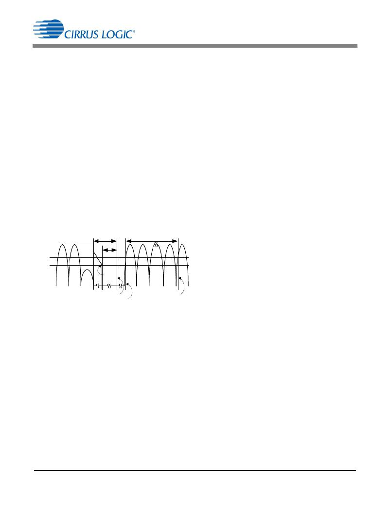
�T� Brownout�
�56� ms�
�for� a� catastrophic� overcurrent� occurrence� by� sensing� sudden�
�Brownout�
�56� ms�
�and� abnormal� operating� currents.� A� second� OCP� threshold,�
�Thresholds�
�Upper�
�Lower�
�Start�
�Timer�
�V� cs(clamp)� ,� determines� whether� a� severe� overcurrent� condition�
�exists.� This� immediately� turns� off� the� gate� drive,� and� the�
�system� enters� a� restart� mode.� The� CS1501� inhibits� all�
�switching� operations� for� approximately� 1.6ms� then� attempts� to�
�restart� normal� operation.�
�Enter� Standby�
�Start� Timer�
�Figure� 20.� Brownout� Sequence�
�Exit� Standby�
�5.11� Overpower� Protection�
�The� CS1501� incorporates� an� internal� overpower� protection�
�(OPP)� algorithm� that� provides� protection� from� overload�
�T� Brownout� =� 8� ms� +� ------------� ?� 128� V� –� V� BP� ?� th� ?� ?� +� 56� ms� [Eq.7]�
�=� 8� +� ---� ?� 128� –� 94.8� ?� +� 56� =� 117ms�
�The� maximum� response� time� of� the� brownout� protection�
�feature� occurs� at� light-load� conditions.� It� is� calculated� by�
�Equation� 7.�
�8� ms�
�5V�
�8�
�5�
�where:�
�conditions.� This� algorithm� uses� the� condition� that� output�
�power� is� a� function� of� the� boost� inductor� (see� section� 5.4�
��Under� moderate� overload,� V� link� may� droop� up� to� 10%� while�
�maintaining� rated� power� and� PFC.� Further� increasing� the� load�
�current� causes� V� link� to� drop� below� the� startup� threshold�
�(~360V).� Below� this� threshold,� the� circuit� switches� the�
�operating� mode� to� startup� with� more� power� available� to� raise�
�V� link� .� As� V� link� reaches� its� nominal� value,� startup� mode� is�
�canceled� and� power� is� now� limited� to� the� rated� value.� If� the�
�V� BP(th)�
�12�
�Brownout� threshold� voltage,� V� BP(th)� =� I� BP(lower)� xR� IAC�
�overload� is� still� present,� this� cycle� will� repeat.�
�If� a� sustained� overload,� or� a� repeated� cycle� of� overload� events�
�is� detected� for� greater� than� 112� ms,� the� CS1501� shuts� down�
�for� 2.5� seconds,� then� attempts� to� restart.�
�DS927F4�
�相关PDF资料 |
PDF描述 |
|---|---|
| VE-231-EV-S | CONVERTER MOD DC/DC 12V 150W |
| IDT71T75602S200PF8 | IC SRAM 18MBIT 200MHZ 100TQFP |
| VI-J5V-CX-F4 | CONVERTER MOD DC/DC 5.8V 75W |
| VI-J4W-CX-F1 | CONVERTER MOD DC/DC 5.5V 75W |
| CENB1020A2403B01 | PS EXT 18W @.75A WALLPLUG E-STAR |
相关代理商/技术参数 |
参数描述 |
|---|---|
| CS1501-FSZR | 制造商:Cirrus Logic 功能描述:IC PFC CONTROLLER DCM OCP - Tape and Reel 制造商:Cirrus Logic 功能描述:IC PFC CTRLR DCM OCP 8SOIC 制造商:Cirrus Logic 功能描述:PFC Controller |
| CS15020_STRADA-IP-2X6-VSM | 功能描述:LENS 0 POS MM (D) MM(H) 制造商:ledil 系列:* 零件状态:有效 标准包装:6 |
| CS15-02GO2 | 制造商:未知厂家 制造商全称:未知厂家 功能描述:Netzthyristoren Phase control thyristors |
| CS15-04GO2 | 制造商:未知厂家 制造商全称:未知厂家 功能描述:Netzthyristoren Phase control thyristors |
| CS15-06GO2 | 制造商:未知厂家 制造商全称:未知厂家 功能描述:Netzthyristoren Phase control thyristors |
发布紧急采购,3分钟左右您将得到回复。