- 您现在的位置:买卖IC网 > PDF目录380066 > CS4216-KL (CIRRUS LOGIC INC) IC EEPROM SRL 256-8BIT 8DIP PDF资料下载
参数资料
| 型号: | CS4216-KL |
| 厂商: | CIRRUS LOGIC INC |
| 元件分类: | 消费家电 |
| 英文描述: | IC EEPROM SRL 256-8BIT 8DIP |
| 中文描述: | SPECIALTY CONSUMER CIRCUIT, PQCC44 |
| 封装: | PLASTIC, LCC-44 |
| 文件页数: | 48/58页 |
| 文件大小: | 799K |
| 代理商: | CS4216-KL |
第1页第2页第3页第4页第5页第6页第7页第8页第9页第10页第11页第12页第13页第14页第15页第16页第17页第18页第19页第20页第21页第22页第23页第24页第25页第26页第27页第28页第29页第30页第31页第32页第33页第34页第35页第36页第37页第38页第39页第40页第41页第42页第43页第44页第45页第46页第47页当前第48页第49页第50页第51页第52页第53页第54页第55页第56页第57页第58页
CONTROL PORT HEADER
The Control Port Header J14 contains the control
port pins, available only in SM4, and the PDN
and RESET pins.
Serial mode 4, SM4, splits the serial data to the
codec into two separate serial ports, the audio
port and the control port. The control port pins
are available on this header. Since CDOUT is
buffered and always driven, it cannot be used on
a shared serial port. Although the INT pin on the
codec is open drain, the default factory configu-
ration for the eval board is an on-board pull-up
resistor and a buffer. Therefore, the INT header
pin cannot share an interrupt pin on a processor
since it is buffered and will always be driven. By
cutting a trace in the J18 jumper, the unbuffered
INT signal, labeled U, can be supplied to the
header. When using the control port, the LB
switch must be off or the control serial port will
be blocked.
PDN and RESET
PDN is buffered and controls the PDN pin on
the CS4216. PDN contains an on-board pull-up
resistor defining the default state as powered.
This pin only needs to be controlled when the
power down feature is used.
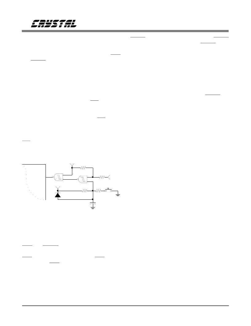
RESET is also buffered and controls the RESET
pin on the codec (see Figure 6). RESET has a
pull-up resistor on the board defining the default
state as not reset or active. This pin only needs
to be controlled when the reset feature on the
codec is needed. Since the codec requires a reset
at power up, a power-up reset circuit is included
on the board. A reset switch is also included to
allow resetting the device without having to re-
move the power supply. The power-up reset plus
switch are logically ORed with the RESET pin
on header J14.
DIGITAL I/O HEADER
The Digital I/O Header, J13 shown in Figure 4,
contains the four digital inputs, DI1-DI4, and the
four digital outputs, DO1-DO4. Note that all
digital I/O except DI1 and DO1 are multifunc-
tion pins and may not be available in a particular
mode. Since DO1 is always a digital output, an
LED is connected to DO1 providing a visual in-
dication that software is writing this bit correctly.
When the LED is on, DO1 is high.
In SM1 and SM2 all four digital inputs and out-
puts are available. In SM3 master sub-modes,
only the first two inputs and outputs are func-
tional. In SM3 slave sub-modes, three inputs and
two outputs are functional. In SM4 only DO1
and DI1 are functional. See the CS4216/8 Data
Sheet for more details.
CLOCKS
The CDB4216/8 provides an on-board default
clock oscillator of 11.2896 MHz (see Figure 7).
This allows all 44.1 kHz and derivative sample
frequencies in SM3 Master sub-mode, SM3
Slave sub-mode, SM4, and the I
2
S mode. The
CS4218 SM3-MM and SM3-MS modes require
a master clock of 16xFs
max
. If using SM1, a
master clock with a frequency that is 512xFs
max
must be supplied. SM2 uses SCLK as the master
clock ant it must be 256xFs
max
. A CLKIN BNC
allows the eval board to be driven from an exter-
VD
VD
RESET
U11
74HC132
R1
47.5k
R4
100
R3
100
SW1A
R2
47.5k
D1
1N4148
CS4216
RESET
2
+ C1
1 uF
8
9
10
11
12
13
Figure 6. Reset Circuit
CDB4216
48
DS83DB4
相关PDF资料 |
PDF描述 |
|---|---|
| CS4216-KQ | 16-Bit Stereo Audio Codec |
| CS4218-KL | 16-Bit Stereo Audio Codec |
| CS4218-KQ | 16-Bit Stereo Audio Codec |
| CS4218 | 16-Bit Stereo Audio Codec |
| CS4220 | 24-Bit Stereo Audio Codec with 3V Interface |
相关代理商/技术参数 |
参数描述 |
|---|---|
| CS4216-KQ | 制造商:CIRRUS 制造商全称:Cirrus Logic 功能描述:16-Bit Stereo Audio Codec |
| CS4217-KL | 制造商:CRYSTAL 功能描述: |
| CS4218 | 制造商:CIRRUS 制造商全称:Cirrus Logic 功能描述:16-Bit Stereo Audio Codec |
| CS4218-KL | 制造商:CIRRUS 制造商全称:Cirrus Logic 功能描述:16-Bit Stereo Audio Codec |
| CS4218-KQ | 制造商:CIRRUS 制造商全称:Cirrus Logic 功能描述:16-Bit Stereo Audio Codec |
发布紧急采购,3分钟左右您将得到回复。