- 您现在的位置:买卖IC网 > PDF目录380086 > CS7620 (Cirrus Logic, Inc.) CCD IMAGER ANALOG PROCESSOR PDF资料下载
参数资料
| 型号: | CS7620 |
| 厂商: | Cirrus Logic, Inc. |
| 英文描述: | CCD IMAGER ANALOG PROCESSOR |
| 中文描述: | CCD成像器模拟处理器 |
| 文件页数: | 31/70页 |
| 文件大小: | 1032K |
| 代理商: | CS7620 |
第1页第2页第3页第4页第5页第6页第7页第8页第9页第10页第11页第12页第13页第14页第15页第16页第17页第18页第19页第20页第21页第22页第23页第24页第25页第26页第27页第28页第29页第30页当前第31页第32页第33页第34页第35页第36页第37页第38页第39页第40页第41页第42页第43页第44页第45页第46页第47页第48页第49页第50页第51页第52页第53页第54页第55页第56页第57页第58页第59页第60页第61页第62页第63页第64页第65页第66页第67页第68页第69页第70页
CS7620
DS301PP2
31
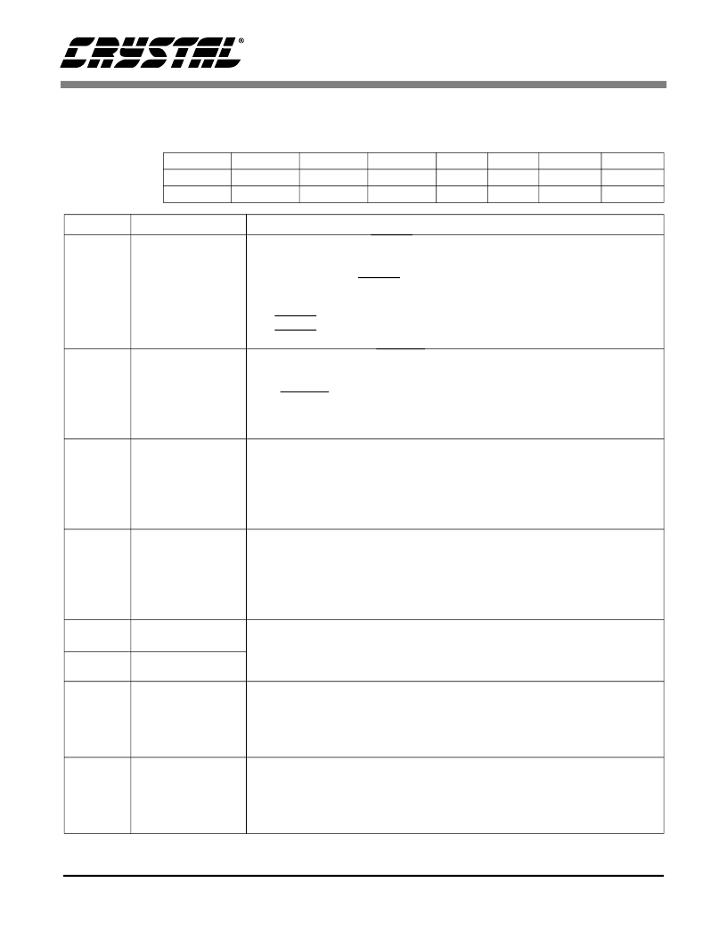
4.5
Operation Control 2
Default = 04h; Read/Write (address 07h).
Bit Number
Bit Name
Default
7
6
5
4
3
2
1
0
pol_hsyncb
0
pol_rd_outb
0
dac2_mode
0
dac1_mode
0
fs_lvl1
0
fs_lvl0
1
gain_cal1
0
gain_cal2
0
Bit
Mnemonic
Function
7
pol_hsyncb
Hsync Polarity:
The HSYNC signal output from the chip defaults to be high
when data is being shifted out of the CCD and low during all other times (the
vertical shift time of each line and idle times). This polarity may be swapped
with this bit so that HSYNC is low when data is being shifted out and high all
other times.
0 - HSYNC is high during horizontal data read out
1 - HSYNC is low during horizontal data read out
Rd_Out Polarity:
The RD_OUT signal output from the chip defaults to be low
when the CCD data readout is being performed and high when not reading out
data from the CCD. The polarity of this signal may be swapped with this bit so
that RD_OUT is high during readout and low when not reading data out. Note
that when this bit is redefined in order to function as a vertical sync signal, this
bit will serve to swap its polarity as well.
Dac #2 Current Mode:
There are two modes for the output current of DAC2.
Default mode provides a current range of 2.2 mA for the 8-bit input word. This
will increment the current by ~8.6 μA per LSB code change. The high current
mode can be selected using this bit to change the current range to 8.7 mA for
the 8-bit input word. This will increment the current by ~34 μA per LSB code
change.
Dac #1 Current Mode:
There are two modes for the output current of DAC1.
Default mode provides a current range of 2.2 mA for the 8-bit input word. This
will increment the current by ~8.6 μA per LSB code change. The high current
mode can be selected using this bit to change the current range to 8.7 mA for
the 8-bit input word. This will increment the current by ~34 μA per LSB code
change.
Full Scale Level:
This is used to set the full scale input range of the CS7620.
Since CCDs have various saturation levels, it is advantageous to set the full
scale input range of the CS7620 to match the saturation level of the CCD
used. Table 9 shows the full scale level choices
Gain Calibration #1:
A calibration of the gain stages is required to insure a
monotonic digital output. In default (‘0’), this calibration is automatically done
after a chip reset and after coming up from power down mode. If the recalibra-
tion after power down is not desired, this bit can be written with a ‘1’ to force
a calibration only after a chip reset.
Gain Calibration #2:
A calibration of the gain stages is required to insure a
monotonic digital output. This calibration is transparent to the user. However,
if the user wishes to force a calibration to occur, he may do so by setting this
bit to ‘1’, which will invoke a gain calibration sequence immediately. This bit
automatically clears itself after a calibration has been initiated.
6
pol_rd_outb
5
dac2_mode
4
dac1_mode
3
fs_lvl1
2
fs_lvl0
1
gain_cal1
0
gain_cal2
相关PDF资料 |
PDF描述 |
|---|---|
| CS7620-IQ | CCD IMAGER ANALOG PROCESSOR |
| CS7622 | CCD Imager Analog Processor |
| CS7622-IQ | CCD Imager Analog Processor |
| CS7654 | CCD COLOR SPACE PROCESSOR WITH ANALOG OUTPUT |
| CS7654-KQ | CCD COLOR SPACE PROCESSOR WITH ANALOG OUTPUT |
相关代理商/技术参数 |
参数描述 |
|---|---|
| CS7620-IQ | 制造商:CIRRUS 制造商全称:Cirrus Logic 功能描述:CCD IMAGER ANALOG PROCESSOR |
| CS7621-4 | 制造商:未知厂家 制造商全称:未知厂家 功能描述:Optoelectronic |
| CS7622 | 制造商:CIRRUS 制造商全称:Cirrus Logic 功能描述:CCD Imager Analog Processor |
| CS7622-IQ | 制造商:CIRRUS 制造商全称:Cirrus Logic 功能描述:CCD Imager Analog Processor |
| CS7631-4 | 制造商:未知厂家 制造商全称:未知厂家 功能描述:Optoelectronic |
发布紧急采购,3分钟左右您将得到回复。