- 您现在的位置:买卖IC网 > PDF目录21889 > CUB5SNK0 (Red Lion Controls)DUAL SINKING OPEN OC OUT CARD PDF资料下载
参数资料
| 型号: | CUB5SNK0 |
| 厂商: | Red Lion Controls |
| 文件页数: | 14/16页 |
| 文件大小: | 0K |
| 描述: | DUAL SINKING OPEN OC OUT CARD |
| 标准包装: | 1 |
| 系列: | * |
| 其它名称: | RLC165 |
�� �
�
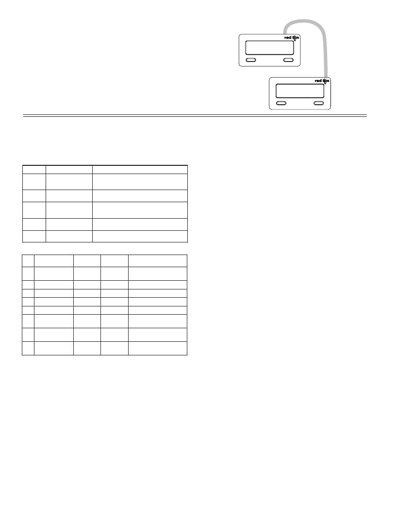
�Copy� Procedure:�
�1.� Connect� the� master� and� receiver� using� the� appropriate� copy� cable.�
�2.� Apply� power� to� the� meters.� The� receiving� meter� must� be� operating� in� the�
�normal� display� mode� (not� programming� mode).�
�3.� On� the� master� meter,� enter� programming� mode� and� proceed� to� the� Copy�
�Program� Settings� parameter� in� Module� 5.� Select� YES� to� begin� copying.�
�4.� During� the� copy� process� (~� 2� sec.),� the� master� meter� displays� an� upload�
�message� (� UP-LOAd� )� while� the� receiver� displays� a� download� message� (� dn-LOAd� ).�
�This� indicates� successful� communication� between� the� master� and� receiver.� If�
�the� receiver� message� is� not� displayed,� be� sure� the� proper� cable� is� connected.�
�5.� When� copying� is� complete,� the� receiver� displays� the� power-up� sequence� and�
�returns� to� normal� operating� mode,� programmed� with� all� the� same� settings� as�
�the� master� meter.� The� master� remains� at� the� COPY� prompt,� ready� to� connect�
�another� receiver� for� copying.�
�MASTER�
�UP-LOAd�
�SEL� RST�
�RECEIVER�
�dn-LOAd�
�SEL�
�RST�
�Node� (meter)�
�Address� Specifier�
�T�
�R�
�Reset�
�P�
�SendingSerialCommandsandData�
�When� sending� commands� to� the� meter,� a� string� containing� at� least� one�
�command� character� must� be� constructed.� A� command� string� consists� of� a�
�command� character,� a� value� identifier,� and� numerical� data� (if� writing� data� to� the�
�meter)� followed� by� a� command� terminator� character,� *� or� $.�
�Command� Chart�
�Command� Description� Notes�
�Address� a� specific� meter.� Must� be� followed�
�N� by� one� or� two� digit� node� address.� Not�
�required� when� node� address� =� 0.�
�Transmit� Value� Read� a� register� from� the� meter.� Must� be�
�(read)� followed� by� a� register� ID� character.�
�Write� to� register� of� the� meter.� Must� be�
�V� Value� Change� (write)� followed� by� a� register� ID� character� and�
�numeric� data.�
�Reset� a� count� value� or� setpoint� output.� Must�
�be� followed� by� a� register� ID� character�
�Block� Print� Request� Initiates� a� block� print� output.� Registers� in� the�
�(read)� print� block� are� selected� in� Print� Options.�
�Command� String� Examples:�
�1.� Node� address� =� 17,� Write� 350� to� the� Setpoint� 1� value�
�String:� N17VF350*�
�2.� Node� address� =� 5,� Read� Counter� A,� response� time� of� 50� msec� min�
�String:� N5TA*�
�3.� Node� address� =� 0,� Reset� Setpoint� 1� output�
�String:� RF*�
�4.� Node� address� =� 31,� Request� a� Block� Print� Output,� response� time� of� 2� msec� min�
�String:� N31P$�
�Transmitting� Data� to� the� Meter�
�Numeric� data� sent� to� the� meter� must� be� limited� to� transmit� details� listed� in� the�
�Register� Identification� Chart.� Leading� zeros� are� ignored.� Negative� numbers�
�must� have� a� minus� sign.� The� meter� ignores� any� decimal� point� and� conforms� the�
�number� to� the� scaled� resolution.� (For� example:� The� meter� ’s� scaled� decimal� point�
�position� is� set� for� 0.0� and� 25� is� written� to� a� register.� The� value� of� the� register� is�
�now� 2.5.� In� this� case,� write� a� value� of� 250� to� equal� 25.0).�
�Note:� Since� the� meter� does� not� issue� a� reply� to� value� change� commands,� follow�
�with� a� transmit� value� command� for� readback� verification.�
�Register� Identification� Chart�
�ID� Value� Description� MNEMONIC�
�A� Counter� A� CTA�
�B� Counter� B� CTB�
�Applicable�
�Commands�
�T,� V,� R�
�T,� V,� R�
�Transmit� Details� (T� and� V)�
�8� digit� positive/7� digit�
�negative� (with� minus� sign)�
�7� digit,� positive� only�
�Receiving� Data� From� The� Meter�
�Data� is� transmitted� from� the� meter� in� response� to� either� a� transmit� command�
�(T),� a� block� print� request� command� (P)� or� a� User� Input� print� request.� The�
�response� from� the� meter� is� either� a� full� field� transmission� or� an� abbreviated�
�transmission,� depending� on� the� selection� chosen� in� Module� 5.�
�C�
�Rate�
�RTE�
�T�
�6� digit,� positive� only�
�Full� Field� Transmission�
�D�
�E�
�F�
�G�
�H�
�Scale� Factor� A�
�Scale� Factor� B�
�Setpoint� 1�
�(Reset� Output� 1)�
�Setpoint� 2�
�(Reset� Output� 2)�
�Counter� A� Count�
�Load� Value�
�SFA�
�SFB�
�SP1�
�SP2�
�CLD�
�T,� V�
�T,� V,�
�T,� V,� R�
�T,� V,� R�
�T,� V�
�6� digit,� positive� only�
�6� digit,� positive� only�
�per� setpoint� Assignment,�
�same� as� Counter� or� Rate�
�per� setpoint� Assignment,�
�same� as� Counter� or� Rate�
�8� digit� positive/7� digit�
�negative� (with� minus� sign)�
�Byte�
�1,� 2�
�3�
�4-6�
�7-18�
�19�
�20�
�Description�
�2� byte� Node� Address� field� [00-99]�
�<SP>� (Space)�
�3� byte� Register� Mnemonic� field�
�12� byte� data� field;� 10� bytes� for� number,� one� byte� for� sign,�
�one� byte� for� decimal� point�
�<CR>� (carriage� return)�
�<LF>� (line� feed)�
�Command� String� Construction�
�The� command� string� must� be� constructed� in� a� specific� sequence.� The� meter�
�does� not� respond� with� an� error� message� to� illegal� commands.� The� following�
�procedure� details� construction� of� a� command� string:�
�1.� The� first� 2� or� 3� characters� consist� of� the� Node� Address� Specifier� (N)� followed�
�by� a� 1� or� 2� character� node� address� number.� The� node� address� number� of� the�
�meter� is� programmable.� If� the� node� address� is� 0,� this� command� and� the� node�
�address� itself� may� be� omitted.� This� is� the� only� command� that� may� be� used� in�
�conjunction� with� other� commands.�
�2.� After� the� optional� address� specifier,� the� next� character� is� the� command� character.�
�3.� The� next� character� is� the� register� ID.� This� identifies� the� register� that� the�
�command� affects.� The� P� command� does� not� require� a� register� ID� character.� It�
�prints� all� the� active� selections� chosen� in� the� Print� Options� menu� parameter.�
�4.� If� constructing� a� value� change� command� (writing� data),� the� numeric� data� is�
�sent� next.�
�5.� All� command� strings� must� be� terminated� with� the� string� termination� characters�
�*� or� $.� The� meter� does� not� begin� processing� the� command� string� until� this�
�character� is� received.� See� Command� Response� Time� section� for� differences� in�
�meter� response� time� when� using� the� *� and� $� terminating� characters.�
�14�
�21� <SP>*� (Space)�
�22� <CR>*� (carriage� return)�
�23� <LF>*� (line� feed)�
�*� These� characters� only� appear� in� the� last� line� of� a� block� print.�
�The� first� two� characters� transmitted� are� the� meter� address.� If� the� address�
�assigned� is� 0,� two� spaces� are� substituted.� A� space� follows� the� meter� address�
�field.� The� next� three� characters� are� the� register� mnemonic,� as� shown� in� the�
�Register� Identification� Chart.�
�The� numeric� data� is� transmitted� next.� The� numeric� field� (bytes� 7� to� 18)� is� 12�
�characters� long.� When� a� requested� counter� or� rate� value� exceeds� the� meter� ’s�
�display� limits,� an� *� (used� as� an� overflow� character)� replaces� a� space� in� byte� 7.�
�Byte� 8� is� always� a� space.�
�The� remaining� ten� positions� of� this� field� consist� of� a� minus� sign� (for� negative�
�values),� a� floating� decimal� point� (if� applicable),� and� eight� positions� for� the�
�requested� value.� The� data� within� bytes� 9� to� 18� is� right-aligned� with� leading�
�spaces� for� any� unfilled� positions.�
�The� end� of� the� response� string� is� terminated� with� a� <CR>� and� <LF>.� After�
�the� last� line� of� a� block� print,� an� extra� <SP>,� <CR>� and� <LF>� are� added� to�
�provide� separation� between� the� print� blocks.�
�相关PDF资料 |
PDF描述 |
|---|---|
| MLBAWT-A1-0000-000W50 | LED XLAMP ML-B WHITE SMD |
| MLBAWT-A1-0000-000VF8 | LED XLAMP ML-B WHITE SMD |
| MLBAWT-A1-0000-000VF7 | LED XLAMP ML-B WHITE SMD |
| ACA-20RM-5-AC4-RL-ALM-C | AMMETER AC 30A 220V W/ALARM RED |
| MLBAWT-A1-0000-000VF5 | LED XLAMP ML-B WHITE SMD |
相关代理商/技术参数 |
参数描述 |
|---|---|
| CUB5TB00 | 功能描述:TIMER & CYCLE COUNTER W/BKLT RoHS:是 类别:工业控制,仪表 >> 计数器 系列:* 其它有关文件:Declaration of Conformity 标准包装:1 系列:99766 计数速率:25Hz 数字/字母数:5 输入类型:机电式脉冲 输出类型:- 电源电压:24V 显示器类型:十进制拨轮 |
| CUB5TCB0 | 功能描述:METER PANEL LCD THERMOCOUPLE RED RoHS:是 类别:工业控制,仪表 >> 仪表 - 面板,数字 系列:CUB5 标准包装:12 系列:* 其它名称:Q7072030 |
| CUB5TCR0 | 功能描述:THERMO METER REFLECTIVE RoHS:是 类别:工业控制,仪表 >> 仪表 - 面板,数字 系列:* 标准包装:12 系列:* 其它名称:Q7072030 |
| CUB5TR00 | 制造商:Red Lion Controls 功能描述:PRESET TIMR & CYCLE COUNTR W/REFL DSPLY 制造商:Red Lion Controls 功能描述:TIMER, ELECTRONIC , 8DIGIT, 9V TO 28V; Supply Voltage Range:9V DC to 28V DC; Panel Cutout Height:39.1mm; Panel Cutout Width:74.9mm; Time Range:- ;RoHS Compliant: Yes |
| CUB5USB0 | 功能描述:USB OPTION CARD RoHS:是 类别:工业控制,仪表 >> 仪表 - 面板,数字 系列:* 标准包装:12 系列:* 其它名称:Q7072030 |
发布紧急采购,3分钟左右您将得到回复。